How to Choose a Custom CNC Automation Lathe Cell
What Is a Tailored CNC Turning Cell
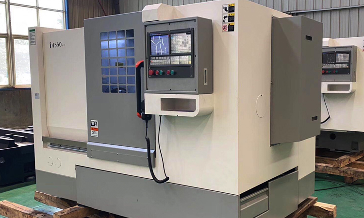
Custom CNC Automation Lathe refers to a CNC turning machine configured with material loading, workholding, part unloading, and quality-control functions for a defined production flow. The “custom” element is not limited to the lathe itself. It includes the way bar stock, blanks, fixtures, collection bins, measurement devices, and operator access are arranged around the machine. A buyer should first understand that computer numerical control controls the programmed machining movement, while automation handles the repeated movement of material and finished parts before and after cutting. A well-matched cell reduces avoidable operator intervention between cycles. It does not automatically solve unstable tooling, inconsistent incoming material, poor chip control, or unclear inspection rules. The right choice depends on the actual part route, production quantity, part geometry, handling method, and acceptable level of manual involvement. Before requesting a proposal, define where a part enters the cell, how it is clamped, what happens after machining, and who verifies the part.
Types of Automation Layouts and Their Best-Fit Conditions
There are several practical layouts for CNC turning automation, and each suits a different input material and production pattern. A bar-fed layout is commonly considered when parts are repeatedly machined from consistent bar stock. A chucking layout is more suitable when the starting material is a casting, forging, pre-cut blank, or an irregular workpiece that cannot travel through a bar feeder. A robot-tended cell can load and unload blanks, transfer workpieces between operations, or place finished parts into trays, but it needs stable pick locations and repeatable gripping surfaces. A simple parts-catching arrangement may suit parts that can be safely released from the spindle and directed into a controlled collection method. Do not choose the highest automation level simply because lights-out operation is desired. A complex handling system is a poor fit when part variation is high, batch sizes are too small to justify changeover effort, or the incoming blanks are inconsistent. For multi-variety, small-batch work, a flexible workholding and quick-change setup can be more useful than a fixed, highly dedicated loader.
| Cell Layout | Best-Fit Input | How It Is Applied | Limit to Check Before Selection |
|---|---|---|---|
| Bar-fed turning cell | Consistent bar stock | A feeder presents stock to the spindle for repeated turning cycles. | Bar shape, straightness, remnant handling, and required secondary operations must be verified. |
| Chucking cell | Pre-cut blanks, castings, or forgings | An operator or robot loads each workpiece into a chuck or dedicated fixture. | Gripper access and repeatable datum surfaces are required for unattended loading. |
| Robot-tended cell | Parts needing loading, unloading, or transfer | A robot moves parts between infeed, machine, inspection, and outfeed positions. | Cycle balance, safe access, and part orientation must be defined before integration. |
| Manual-assisted cell | Frequent changeovers or uncertain demand | The machine automates machining while an operator handles selected loading or inspection tasks. | It will not provide long unattended periods when manual tasks remain within every cycle. |
Features to Specify Before You Define the RFQ
Your RFQ should describe the cell as a linked manufacturing process rather than a request for “a lathe with automation.” Start with the workpiece drawing, annual or monthly demand range, planned batch size, raw-material form, finished-part handling requirement, and inspection points. Then state the desired operator role. For example, the operator may load material at the beginning of a shift, replenish trays between batches, perform first-off approval, or respond only to alarms. These are very different operating models. Ask the supplier to show the proposed sequence from material arrival through finished-part collection. At MAKCNC, relevant machine foundations may use high-strength cast iron, including resin-sand castings, with aging treatment intended to support long-term rigidity and accuracy. Core transmission components may use high-precision Taiwan or German-brand ballscrews and guideways. These construction details can support a stable machine platform, but they do not replace application validation for your specific part, tooling, fixture, or automation interface.
- Specify the raw material: State whether the cell receives bar stock, sawn blanks, forgings, castings, or customer-supplied semi-finished parts. Material input determines the feeder, gripper, fixture, and guarding concept.
- Define workholding: Identify chucking surfaces, locating datums, clamping restrictions, and whether soft jaws, collets, or dedicated fixtures are needed. A robot cannot reliably load a part when the workholding datum is unclear.
- Describe part exit: Confirm whether parts can drop safely, need a catcher, must be placed in trays, or require orientation for a later process.
- Set inspection ownership: State which dimensions require first-piece verification, periodic checks, in-cycle measurement, or offline inspection.
- List changeover conditions: Include every planned part family, tooling change, jaw change, feeder adjustment, and program change expected in normal production.
Map Material Flow Steps to Prevent Unattended Cycle Bottlenecks
An unattended cycle only works when every non-cutting step is mapped with the same care as the turning program. Production teams often focus on spindle time and overlook the interruptions caused by depleted bar stock, a part that fails to eject, a full collection bin, or an inspection task that requires an operator every few cycles. The practical approach is to document one complete part flow and identify the trigger, device, verification point, and recovery action for each step. The table below is a planning tool, not a promise of unattended output. It helps determine whether a bar feeder, chucking system, ejection method, and inspection plan operate at compatible intervals. If one step requires more frequent attention than the others, that step sets the actual unattended period.
| Process Step | Selection Question | Suitable Approach | Bottleneck or Boundary to Check |
|---|---|---|---|
| Bar stock input | Can the part be made from repeatable bar stock? | Use a bar feeder when stock form and bar preparation are consistent. | Check bar remnants, stock variation, feeder replenishment, and whether the part needs operations beyond turning. |
| Chucking and locating | Does every blank present a stable locating surface? | Use chuck jaws, collets, or a dedicated fixture matched to the established datum. | Do not assume a robot can correct inconsistent blank orientation or poor datum condition. |
| Part ejection | Where does the finished part go after cutoff or unclamping? | Use a parts catcher or controlled outfeed when part condition and geometry permit. | Check part temperature, chip carryover, surface protection, entanglement risk, and bin capacity. |
| Inspection | Which characteristics need verification during production? | Use planned first-piece, periodic, or in-process inspection based on the control requirement. | Automation is not suitable for an inspection method that still needs constant manual judgment or frequent adjustment. |
| Exception recovery | What happens after an alarm, tool change, or misloaded part? | Document a clear operator recovery procedure and restart condition. | Do not call a cell unattended if recovery requires undocumented manual alignment or uncertain re-homing. |
Consider an illustrative production situation: a manager plans to turn a family of short shaft parts from bar stock. The cutting cycle is stable, but the finished parts must remain separated to avoid cosmetic damage. A basic collection bin may therefore be unsuitable even if the machining operation itself is repeatable. The cell may instead require a catcher, controlled placement, divided trays, and a defined tray-change interval. If the same manager later introduces a forged flange with a nonuniform profile, the original bar-fed concept no longer fits. The cell may need a chucking arrangement and a gripper designed around the available handling surfaces. This is not a documented customer case. It shows why material input and finished-part output must be evaluated together rather than selected as isolated accessories.

Applications That Justify Automation and Conditions That Do Not
A tailored turning cell is generally a stronger fit when the part family has repeatable loading conditions, a defined workholding datum, predictable chip behavior, and sufficient recurring demand to support setup planning. It can also fit multi-variety, small-batch production when the changeover process is deliberately designed around reusable fixtures, documented offsets, and practical operator access. MAKCNC states that its equipment can support multi-face machining in one clamping for applicable production needs, which may reduce transfers between setups when the part and process allow it. This capability must still be confirmed against the drawing, tool access, tolerances, and required operations. For milling features that cannot reasonably be completed within the turning process, a linked professional cnc machining center solution may be relevant to the overall route. Automation is a weaker fit when incoming blanks vary substantially, the part has no reliable gripping area, demand is unpredictable, or the inspection plan depends on frequent manual evaluation. In those situations, a manual-assisted cell or phased automation project may control risk more effectively.
Price Factors and a Practical Cost Breakdown
The price of a turning automation project changes with the machine configuration, automation scope, workholding, safety equipment, inspection devices, software interfaces, installation requirements, and acceptance plan. Buyers should avoid comparing proposals only by the base lathe price. A lower initial machine price may omit the feeder, gripper, catcher, fixture design, tray system, or inspection interface needed for the intended workflow. Conversely, an oversized robot or complex transfer system may add cost without solving the actual constraint. Ask each supplier to separate the quotation into functional blocks so purchasing, production, and engineering can review what is included. No fixed project price can be stated without drawings, material form, output expectations, and the required handoff between operations.
| Cost Area | What Changes the Cost | Buyer Action |
|---|---|---|
| Base CNC lathe | Machine size, spindle arrangement, control configuration, and required turning capacity | Provide the largest part envelope and planned workpiece range instead of only one sample part. |
| Material handling | Bar feeder, robot, infeed station, gripper design, trays, and outfeed method | Provide photos or samples of raw blanks and finished-part packaging requirements. |
| Workholding and tooling | Chucks, jaws, collets, fixtures, toolholders, and changeover requirements | Identify all planned part families and their locating surfaces before quotation. |
| Inspection integration | Measurement method, part presentation, data requirements, and reject handling | State which dimensions need production checks and who approves exceptions. |
| Commissioning support | Site readiness, operator training, acceptance criteria, and service scope | Agree on responsibilities before issuing a purchase order. |
User Guide for Layout Review, Acceptance, and Daily Operation
Before installing a cell, review the complete operating sequence with production, maintenance, quality, and safety personnel. Confirm where operators load consumables, remove finished trays, change tools, access the chuck, clear chips, and recover from an alarm. Ensure that emergency stops, guarding, access doors, and manual-mode actions are part of the layout review rather than added after the handling equipment is positioned. During acceptance, test the actual part family and its normal material condition where possible. A demonstration using an ideal sample does not prove that mixed lots, tool wear, chip accumulation, or routine changeovers are controlled. Create a start-of-shift checklist that includes material level, workholding condition, tool status, coolant and chip-management checks, collection capacity, and the inspection schedule. MAKCNC typically offers a 12-month machine warranty after acceptance and lifetime paid service; individual tender requirements may request different coverage, such as three years of free warranty. Confirm the warranty and support terms in the final contract rather than relying on a general expectation.
- Map the current route from raw material to packed finished part.
- Classify every operator action as loading, quality verification, replenishment, adjustment, or recovery.
- Decide which actions can be automated without creating difficult changeovers.
- Provide drawings, material details, part samples where available, and expected production mix to the supplier.
- Review a proposed layout for access, guarding, chip handling, maintenance, and finished-part storage.
- Set acceptance criteria that cover machining quality, handling reliability, recovery actions, and operator training.
MAKCNC as a CNC Turning Cell Supplier
When evaluating a supplier, review whether the company can discuss the machine, the automation boundary, and the practical production conditions as one project. MAKCNC was established in 2016 and has multiple production lines and sample-machine inventory. The stated order lead time is generally one to six months, depending on the project. There is no mandatory minimum order quantity, so a single machine can be purchased, while multi-machine orders may receive improved commercial terms for pricing, delivery, or after-sales service. For a tailored cell, this matters because buyers may wish to validate one production unit before considering a wider rollout. Explore customized cnc machines and machining centers from makcnc when the project requires a defined workflow beyond a standard machine configuration. MAKCNC also states that its service network typically responds within eight hours and may arrive on site within forty-eight hours for fault handling, subject to location and agreed service conditions.
FAQ of CNC Turning Automation Cells
Should a buyer automate bar loading before automating part unloading?
Not always. Bar loading is a logical first step when the workpiece is repeatedly made from consistent bar stock and the main interruption is material replenishment. However, the choice should follow the actual bottleneck. If operators spend more time separating finished parts, protecting surfaces, or performing frequent manual checks, automated loading alone may not materially extend the unattended cycle. Map the full sequence first. Identify how long each task takes, how often it occurs, and whether it can be completed safely without operator judgment. A bar feeder may be unsuitable for short runs with frequent stock changes, irregular material, or parts that start from pre-cut blanks. In those cases, a chucking cell with a simple outfeed arrangement may be a more practical first phase.
Can one automation cell handle several different turned parts?
It can, but flexibility must be designed into the cell instead of assumed. Review whether the same gripper can handle each part, whether workholding jaws or collets can be changed efficiently, whether the part catcher accommodates the full size range, and whether the inspection method remains valid across the family. A cell intended for multiple variants should have a documented changeover sequence covering tooling, offsets, fixtures, automation recipes, and quality approval. It is not a suitable approach when each part needs a fundamentally different loading orientation or fixture concept and changeovers would become too frequent or error-prone. For buyers with uncertain production mix, start by defining the core part family and optional future variants. This gives the supplier a clear basis for deciding which elements should be dedicated and which should remain adjustable.
What should be included with the first RFQ?
A useful first RFQ includes the part drawing, material form, estimated demand range, target batch size, current machining route, required operations, quality checkpoints, and preferred level of operator involvement. Add photos of the raw blank and the desired finished-part packaging if handling is part of the project. State whether the part will be produced from bar stock, castings, forgings, or pre-cut blanks. Also identify known concerns such as chip buildup, surface protection, difficult gripping, multiple setups, or a need to connect with downstream milling or inspection. Request that the supplier identify assumptions and exclusions in the proposal. This protects both sides from treating an illustration as a complete solution. A properly defined RFQ makes it easier to compare a standard cnc lathing machine with a more integrated automation-cell proposal.
Submit your drawings and expected part flow to MAKCNC for selection advice and a current project quotation.