How Does a CNC Turning and Milling Composite Machine Work
A CNC Turning and Milling Composite Machine is a machine tool that performs turning, milling, drilling, and sometimes gear cutting or grinding, all within a single work-holding setup. Instead of moving a part between a lathe and a machining center, the workpiece stays clamped once while multiple tool systems approach it from different axes. Engineers researching this equipment usually want a straight answer to one question: does the part geometry justify the machine cost, or is a standard lathe plus a separate mill still the better economic choice? This article breaks down the mechanics, the axis logic, and the decision criteria so production planners can answer that question with actual numbers instead of guesswork.
What Is a Turn-Mill Composite Machine
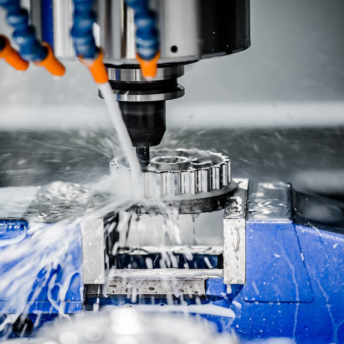
A turn-mill composite machine, sometimes called a mill-turn center, is a CNC platform that merges a rotating spindle (for turning) with a driven tool spindle (for milling, drilling, and tapping) on the same bed. The part rotates like it would on a lathe, but live tooling can also spin independently, cutting flats, cross-holes, and off-center features without the part ever being unclamped. This is fundamentally different from a standard CNC machining center, where the spindle carries the cutting tool and the table or head provides positioning, but there is no main rotating chuck spindle for turning operations. The distinction matters because it determines whether a shop needs one machine or two to finish a part.
Types of Turn-Mill Composite Machines
Not every mill-turn platform is built the same way, and the configuration affects what part families it can realistically handle.
- Single-turret turn-mill lathes — a turning center with one turret carrying both static and live tools. Good for shafts, flanges, and pump housings that need occasional side-milling or cross-drilling.
- Dual-spindle turn-mill machines — one spindle holds the part for the first operations, then a second spindle picks it up to finish the back face, eliminating a manual re-fixturing step entirely.
- Twin-turret / B-axis mill-turn centers — higher-end configurations with an articulating milling head, used for complex aerospace or medical parts requiring compound angles.
- CNC inclined bed lathes with live tooling — a mid-range option that adds basic C-axis milling capability to a conventional inclined-bed lathe layout. See the CNC inclined bed lathe for a base-platform reference point.
Technical Breakdown of Spindle Roles, Live Tooling, C/Y Axes, and Single-Setup Part Flow
This is the section that actually determines whether a mill-turn machine solves your problem or adds cost without benefit. Each component plays a distinct role, and getting the specification wrong changes what the machine can and cannot do.
Main Spindle vs. Sub-Spindle
The main spindle holds and rotates the raw stock for turning operations — OD turning, facing, threading. A sub-spindle, when present, is a second chuck that receives the part after the first side is finished, so the operator (or the machine automatically) transfers the part internally instead of manually flipping it in a vise. If your parts require features on both ends — such as a shaft with a keyway on one end and a threaded bore on the other — a sub-spindle machine removes one full re-setup. Without it, you either accept a manual second operation or you accept location error from re-chucking.
Live Tooling
Live tooling means the tool itself rotates, powered by an independent motor in the turret, rather than staying static while the part spins. This lets the machine drill a cross-hole, mill a flat, or cut a keyway on a part that is still chucked and turning-ready. Get this wrong — specify a machine with only static tooling — and any off-axis feature forces a second operation on a mill, defeating the purpose of buying a turn-mill machine in the first place.
C-Axis and Y-Axis
The C-axis lets the main spindle stop and index to a precise rotational position, which is what allows live tools to cut a feature at an exact angular location — a bolt pattern, a D-flat, a radial hole. Without C-axis control, live tooling can only cut continuous features like knurls, not positioned ones. The Y-axis adds vertical offset to the milling tool path, allowing off-center slots and pockets rather than only features on the centerline. A part with an off-axis pocket cannot be machined accurately without Y-axis travel — the toolpath would have to be approximated, which shows up as poor surface finish or dimensional drift.
Single-Setup Part Flow
Here is the practical sequence on a dual-spindle turn-mill machine, using a stepped shaft with a cross-drilled hole and a threaded end as an example:
- Bar stock feeds into the main spindle and is faced and rough-turned to the first diameter profile.
- The turret indexes to a live tool, and the C-axis holds position while a cross-hole is drilled at 90 degrees to the centerline.
- The sub-spindle advances, grips the finished end, and the main spindle releases — no manual handling.
- The back face is turned, chamfered, and threaded while the part is held by the sub-spindle.
- The finished part drops or is unloaded automatically.
That entire sequence, on a two-machine setup (lathe plus mill), would require at minimum one manual transfer, one re-fixturing, and one alignment check — each adding time and a chance for concentricity error.
Features That Actually Affect Output Quality
Beyond the axis configuration, a few structural and control features determine real-world performance:
- Cast iron bed construction — high-strength cast iron, typically resin-sand cast and stress-relieved through aging treatment, holds geometric accuracy over years of use rather than drifting under thermal or cutting load.
- Ballscrew and guideway quality — core transmission components sourced from established Taiwanese or German brands directly affect repeatability, especially on parts with tight positional tolerances.
- Anti-vibration and compensation systems — intelligent feed-forward control and quadrant-transition compensation reduce chatter marks, quadrant glitches, and overcut lines, which matter heavily in mold and die work where surface finish is inspected visually and dimensionally.
Mill-Turn Machining Applications
Multi-axis machining on a combined platform fits certain part families better than others. Good candidates include:
- Stepped shafts with cross-holes, flats, or keyways at multiple angular positions
- Small-batch, high-mix production where fixture changeover time dominates the schedule
- Mold components and inserts requiring both round profiles and milled cavities in one reference frame
- Medical and hydraulic fittings where concentricity between turned and milled features is tightly toleranced
Parts that are purely rotational with no off-axis features — simple bushings, spacers, standard studs — usually do not justify a mill-turn machine. A conventional lathe handles them faster and at lower capital cost. For high-volume flat or box-shaped parts with no turning features at all, a vertical CNC machining center is the more appropriate tool.
CNC Turn-Mill Composite Machine Price Factors
Pricing on turn-mill equipment varies more than on standard lathes because so much depends on configuration, not just machine size. Key cost drivers:
| Factor | Impact on Price |
|---|---|
| Single vs. dual spindle | Dual-spindle adds meaningful cost but removes manual re-setup labor |
| Live tooling count | More driven tool stations increase turret cost and cycle flexibility |
| C/Y axis inclusion | Y-axis specifically raises cost due to added slide and control complexity |
| Ballscrew/guideway brand | Taiwanese or German-branded components cost more but hold tolerance longer |
| Control system | Advanced compensation software (anti-vibration, quadrant correction) adds to base price |
| Order volume | Single-unit purchase is accepted, but multi-unit orders typically unlock better pricing, lead time, or service terms |
There is no fixed minimum order — a single machine can be purchased — but batch orders generally receive more favorable commercial terms on price, delivery, or after-sales support.
Turn-Mill Machine User Guide and Common Mistakes
Before running production on a new mill-turn setup, walk through this checklist:
- Confirm chuck jaw pressure is matched to part wall thickness — over-clamping thin-wall parts causes distortion once the clamp releases.
- Verify C-axis zero position after any tool change on the live tooling turret; a missed reference causes angular features to land in the wrong position.
- Check coolant delivery to live tools separately from the main turning coolant line — driven tools generate localized heat that main-spindle coolant alone may not reach.
- Run a dry cycle with tool offsets loaded before cutting the first article, especially on Y-axis programs where off-center paths are harder to visually verify.
- Schedule preventive maintenance on ballscrews and guideways — neglect here is the most common cause of accuracy loss reported in field service calls.
Common mistakes we see raised in technical discussions include specifying static tooling for parts that actually need positioned features, skipping sub-spindle synchronization checks, and underestimating spindle warm-up time on precision mold work.
MAKCNC as a Turn-Mill Composite Machine Supplier
MAKCNC has operated multiple production lines since 2016 and maintains sample machine inventory for faster evaluation and delivery, generally within one to six months depending on configuration. Our facility operates under ISO9001:2015 certification. Machine frames use high-strength cast iron, resin-sand cast and aged for long-term rigidity, and core transmission parts are sourced from established Taiwanese or German suppliers. For mold-industry customers dealing with overcut marks, quadrant glitches, or chatter lines, our control systems integrate feed-forward and quadrant-transition compensation, and our machines support one-setup multi-face machining for mixed small-batch production. Standard warranty covers 12 months post-acceptance with paid lifetime service available; select tender projects can include extended three-year free warranty terms. Our service network targets an 8-hour response and 48-hour on-site resolution for reported issues. Browse our horizontal CNC machining center lineup or review documented project cases to see deployed configurations, or visit our company background page for manufacturing details.
FAQ About CNC Turning and Milling Composite Machines
How does a CNC turning and milling composite machine work?
It holds a part in a rotating chuck for turning operations while live tooling, indexed by a C-axis and sometimes offset by a Y-axis, cuts milled, drilled, or off-center features without removing the part from the fixture.
What is a turn-mill composite machine?
It is a CNC platform that combines lathe-style turning with milling-center capability on one bed, allowing a single work-holding setup to produce both rotational and non-rotational features.
How does mill-turn machining reduce setups?
By keeping the part in one chuck or transferring it internally between a main and sub-spindle, mill-turn machining removes manual re-fixturing steps that would otherwise be needed to move a part between a separate lathe and mill, cutting cycle time and reducing alignment error.
Is there a minimum order quantity for these machines?
No strict minimum applies — a single unit can be purchased — though multi-unit orders often receive improved pricing, lead time, or service terms.
If you are evaluating a customized CNC machine configuration for a specific part family, send your drawings or tolerance requirements and we can advise on spindle, tooling, and axis selection before you commit to a quote.