How to Test a High Rigidity CNC Machine Tool
What Is a High Rigidity CNC Machine Tool
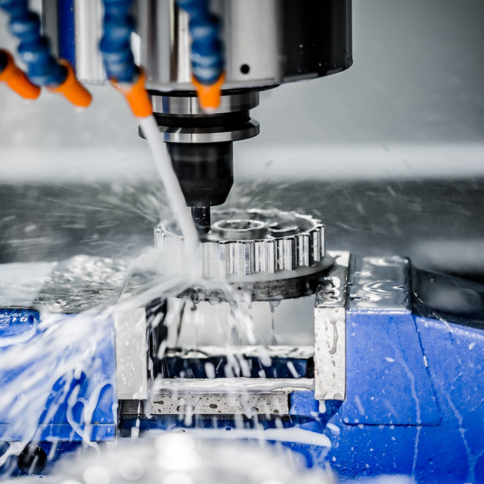
High Rigidity CNC Machine Tool is a machine designed to resist deformation and unwanted vibration while the spindle, tool, workpiece, and machine structure are under machining load. For manufacturing engineers, rigidity is not simply a catalog term. It affects whether a machine can maintain part geometry, surface quality, tool life, and process stability during real cutting. A machine may appear heavy and stable when idle but still show excessive movement at the spindle, table, turret, or workholding interface when forces are applied. This is why technical evaluation should focus on measured behavior rather than appearance alone. A useful assessment combines structural inspection, static deflection testing, vibration testing, and an actual cutting test. The result is a more reliable basis for comparing machines before issuing an RFQ or finalizing an equipment specification.
Machine rigidity includes the stiffness of the base, column, spindle housing, table, guideway system, ball screw support, toolholder, and fixture arrangement. It also includes the interaction of these parts. A stiff casting cannot compensate for a weak spindle interface, and a capable spindle cannot overcome poor workholding. For machining centers, the load path usually runs from cutter to spindle, spindle head, column, base, table, fixture, and workpiece. For turning equipment, it runs through the cutting tool, turret, carriage, bed, chuck, and part. The right High Rigidity CNC Machine Tool should therefore be evaluated as a complete system, not as a single structural component.
Types of Machines That Need Rigidity Testing
Rigidity testing applies to more than one machine configuration. The right test arrangement depends on the intended operation, workpiece shape, tool extension, and cutting direction. A vertical machine is often assessed for spindle-to-table stiffness and column behavior under side load. A horizontal machine may require additional attention to pallet, tombstone, and fixture stability. A CNC lathe needs inspection of bed stiffness, turret support, chuck condition, tailstock support where applicable, and part clamping. The practical recommendation is to select a test method that matches the work you intend to run. A general demonstration is useful for an early review, but it does not replace a test based on your real component geometry or cutting challenge.
| Machine Type | Primary Rigidity Concern | Best Evaluation Scenario | When This Method Does Not Apply |
|---|---|---|---|
| Vertical machining center | Column, spindle head, table, and fixture load path | Milling faces, pockets, bores, and mold features | It does not fully represent long turning workpieces or chucking behavior |
| Horizontal machining center | Spindle, pallet, tombstone, and multi-face fixture stiffness | Multi-face machining in one clamping setup | It may not represent tall unsupported parts on a vertical table |
| Inclined bed CNC lathe | Turret, carriage, bed, chuck, and workpiece support | Turning, boring, grooving, and interrupted cuts | It does not evaluate milling-column behavior |
For buyers comparing turning equipment, a cnc inclined bed lathe should be reviewed with the same discipline as a machining center. Check how the part is clamped, how far it extends from the chuck, whether a tailstock or support is needed, and whether the selected toolholder creates excessive overhang. A High Rigidity CNC Machine Tool can still deliver poor results if the test part is held in a way that would never be accepted in production. The limit is clear: machine testing cannot correct a weak fixture or an impractical part setup.
Features to Inspect Before Measuring Machine Rigidity
The first inspection should focus on the structure and motion components that influence load resistance. MAKCNC machine bodies commonly use high-strength cast iron, including resin-sand castings, with aging treatment intended to support long-term accuracy and rigidity. Core transmission components such as ball screws and guideways may use high-precision components from Taiwan or Germany. These facts are relevant, but they are not a substitute for measurement on the quoted machine. The recommended approach is to request the construction details, confirm the applicable configuration, and then test the machine using a documented procedure. This suits buyers preparing a technical comparison. It is less useful when a purchase decision is based only on basic hobby use, where production consistency is not the primary concern.
- Machine base and column: Look for a continuous load path between the spindle area and the base. If this path moves under load, the cutter can remove material unevenly and produce taper or inconsistent wall thickness.
- Guideways and ball screw supports: Ask how these components are arranged and supported. Weak support can appear as position variation, poor interpolation, or unstable motion under changing cutting loads.
- Spindle and tool interface: Check spindle taper condition, toolholder seating, tool extension, and retention. A long tool extension can create vibration even when the main structure is stiff.
- Fixture and workholding: Review the full setup. A weak vice, chuck, fixture plate, or part clamping method may be mistaken for machine deflection.
- Control functions: For demanding mold work, MAKCNC systems may integrate intelligent feedforward and quadrant-jump compensation to help address overcut marks, quadrant marks, and chatter-related patterns. Verify whether these functions are included in the selected configuration.
The main lesson is simple. Do not approve a High Rigidity CNC Machine Tool from casting weight, brochure photographs, or a list of imported components alone. Those details can support an initial shortlist, but the buyer should ask for measurable evidence under a controlled setup. A feature review fits early supplier screening. It does not establish how the machine will behave with your cutter, fixture, material, and production program.
How Static Deflection Tap Testing and Cutting Tests Reveal Real Performance
A High Rigidity CNC Machine Tool should be examined under conditions that expose movement and vibration. Three tests provide different evidence: static deflection testing, tap testing, and cutting testing. Static deflection testing shows how much a machine component moves under a controlled force. Tap testing helps identify vibration behavior and natural frequency response. A cutting test shows whether the complete machine-tool-workpiece system remains stable in actual material removal. The correct conclusion is not that one test is enough. Each test identifies a different risk, so buyers should request all three when a machine will handle difficult materials, long tool reach, deep cavities, interrupted cutting, or close-tolerance work.
| Test Method | What to Measure | What It Affects in Production | What Can Go Wrong if Ignored |
|---|---|---|---|
| Static deflection test | Displacement at the spindle, tool point, table, turret, or fixture while a controlled force is applied | Part size, straightness, taper, bore quality, and consistency under cutting load | A machine may cut acceptable trial parts lightly but move excessively during heavier operations |
| Tap testing | Vibration response after a controlled impact at the spindle-tool assembly or workholding system | Chatter risk, usable spindle-speed ranges, surface finish, and cutter life | The buyer may select cutting conditions that excite vibration and leave chatter marks |
| Cutting test | Actual dimensions, surface condition, sound, chip formation, tool wear, and visible vibration during machining | Whether the full process remains stable under realistic conditions | Static results may look good while the real cutter, fixture, and material combination performs poorly |
Static Deflection Test Procedure
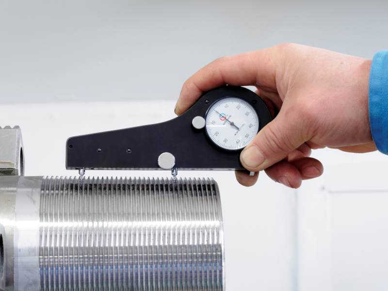
For a static deflection test, mount a representative toolholder or test bar in the spindle, or place a representative tool setup on the turret. Position a dial indicator or suitable displacement measurement device at the point of interest. Apply a controlled force in the direction that resembles the expected machining load, then record movement at the spindle nose, tool point, table, fixture, or workpiece support. Repeat the procedure after changing the axis position because overhang can change as the spindle head or table moves. The buyer should request the force direction, loading point, measurement point, machine axis position, fixture arrangement, and recorded displacement. This method fits comparisons between similar machines. It does not predict every machining result because real cutting adds heat, tool wear, changing chip load, and dynamic vibration.
Tap Testing and Cutting Test Procedure
Tap testing should be performed with the same toolholder, cutter extension, and fixture arrangement planned for production. The purpose is to observe how the assembled system responds to a controlled impact. A different tool extension can change the response, so a short demonstration tool is not enough when the intended process requires a long reach. For the cutting test, use the intended workpiece material, cutter type, cutting direction, tool extension, clamping method, and process sequence wherever possible. Record surface patterns, machine sound, chip behavior, measured dimensions, and tool condition. A High Rigidity CNC Machine Tool should be compared using the same test conditions across suppliers. Changing tools, workholding, or programs between demonstrations makes the results unsuitable for a fair decision.
High Rigidity CNC Machine Tool Applications and Test Priorities
Different applications place force in different directions, so the test should reflect the actual production risk. Mold machining often needs stable finishing performance, controlled multi-axis motion, and reduced visible marks on shaped surfaces. Deep cavity work can involve long tools, making toolholder and spindle assembly behavior especially important. General component machining may place more emphasis on repeatable bores, face flatness, and fixture stability across repeated setups. Turning applications may require attention to unsupported part length, boring bar extension, interrupted cuts, and chucking force. The recommendation is to define the most difficult feature on your part before asking for a test. This fits engineers specifying equipment for recurring production. It is less relevant if the machine will only perform simple, low-load operations.
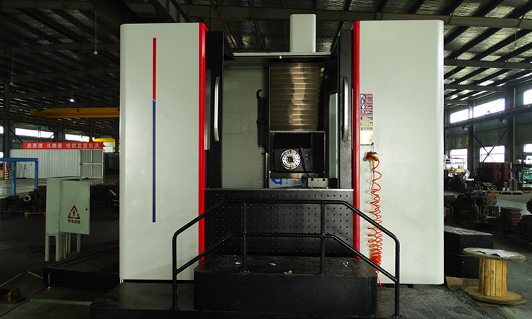
For multi-variety, small-batch production, the ability to complete multiple faces in one clamping can reduce cumulative setup error. However, this benefit depends on fixture design and access to the required surfaces. A High Rigidity CNC Machine Tool is particularly useful when a part must maintain relationships between features machined from different directions. Before specifying a horizontal or vertical platform, identify which features must remain aligned after reclamping and which can be completed in a single setup. For buyers reviewing vertical equipment, the vertical cnc machining center mv1380 page can support an initial model review, but final selection should still follow a workpiece-specific test plan.
High Rigidity CNC Machine Tool Price Factors
Price should be evaluated as a scope comparison rather than a single machine figure. A quotation may differ because of machine configuration, control system, spindle selection, axis travel, tool magazine arrangement, workholding, optional equipment, inspection requirements, packing, shipping terms, commissioning scope, and after-sales terms. The sensible decision is to compare like-for-like offers using a written technical schedule. This approach is appropriate for purchasing managers and engineering teams who need to defend a capital-equipment decision. It does not apply when quotations are based on different machine classes or when the buyer has not yet defined the workpiece and production target.
| Quotation Factor | Buyer Action | Why It Matters |
|---|---|---|
| Machine configuration | List required spindle, control, toolholding, and workholding items separately | Prevents a low starting price from hiding needed options |
| Test requirement | Attach the deflection, tap, and cutting-test procedure to the RFQ | Makes technical acceptance part of the purchase discussion |
| Lead time | Confirm the quoted delivery schedule for the selected configuration | MAKCNC states a typical lead time of one to six months, which may vary by order scope |
| Service terms | Confirm warranty start point, response process, and local support arrangement | MAKCNC generally provides a twelve-month warranty after machine acceptance and lifetime paid service |
High Rigidity CNC Machine Tool User Guide for Buyer Acceptance
Use a controlled acceptance plan rather than a general machine demonstration. First, provide the supplier with a drawing, material, critical features, required surface condition, and expected tooling. Next, define the fixture and workholding method. Then require the supplier to document the machine model, spindle configuration, toolholder, cutter extension, workpiece clamping, program, and measurement locations. During testing, observe static deflection results, tap-test response, and the completed cutting sample. After machining, inspect the relevant geometry and surface condition using the same measurement method planned for production acceptance. Finally, record the setup so it can be repeated. This procedure gives the buyer a usable audit trail. It does not remove the need for operator training, correct tooling, maintenance, and proper factory installation after delivery.
- Identify the highest-load or highest-risk feature on the workpiece.
- Specify the real material, fixture concept, cutter type, and tool extension.
- Request static deflection measurements at relevant machine positions.
- Request tap testing for the actual spindle-tool-fixture assembly.
- Run a cutting test using a documented and repeatable program.
- Inspect the finished sample and compare it with the drawing requirements.
- Include the agreed acceptance records in the purchasing file.
High Rigidity CNC Machine Tool Supplier Selection
A supplier should be able to discuss the machine structure, the test setup, the limits of the test, and the configuration options that affect rigidity. MAKCNC was established in 2016 and has multiple production lines and sample machine inventory. The company supplies CNC lathing machines, CNC machining centers, and CNC machines, with no mandatory minimum order quantity for a single machine purchase. Larger orders may receive improved commercial terms related to price, delivery, or after-sales support. For projects requiring a non-standard setup, buyers can review customized cnc machines and machining centers from makcnc before issuing a detailed request.
Service requirements should also be confirmed before purchase. MAKCNC generally offers a twelve-month warranty after complete machine acceptance and lifetime paid service. Some tender projects may require a longer free warranty period, such as three years, and these terms should be written into the contract rather than assumed. A mature service network may provide an eight-hour response commitment and onsite fault handling within forty-eight hours, subject to the applicable support arrangement. A High Rigidity CNC Machine Tool should be selected with both technical evidence and a clear service plan, especially when downtime can affect production schedules.
FAQ of High Rigidity CNC Machine Tool Testing
Can machine weight prove rigidity?
No. Weight can indicate that a machine has substantial structure, but it does not show where movement occurs under load. A heavy base may coexist with a flexible toolholder, weak fixture, unsuitable cutter extension, or vibration-sensitive spindle assembly. The better method is to measure static deflection and conduct a cutting test using a representative setup. This is especially relevant for mold machining, deep pockets, boring, and interrupted cutting. Weight can still be a useful background detail during early screening, but it should not be used as the final acceptance criterion for a High Rigidity CNC Machine Tool.
Should buyers request both tap testing and a cutting test?
Yes, when the intended application has a meaningful risk of chatter, long tool reach, demanding surface requirements, or variable material removal. Tap testing identifies vibration behavior in the assembled system, while cutting testing shows the effect of actual machining conditions. One cannot fully replace the other. For simple, low-load production, a documented cutting test may be sufficient if the setup closely matches the planned work. For demanding applications, requesting both tests creates a stronger technical basis for selecting a High Rigidity CNC Machine Tool and setting realistic acceptance expectations.
If you are looking for a High Rigidity CNC Machine Tool supplier, contact MAKCNC for the latest quotation and technical selection advice.