
3 Axis CNC Machine Setup Operator Guide
3-Axis CNC Machine refers to a computer numerical control milling system that moves the cutting tool or workpiece along three perpendicular linear axes—X, Y, and Z—simultaneously. This basic kinematic structure removes material from a solid block through precise, programmable commands. The spindle moves up and down (Z), while the table shifts left-to-right (X) and front-to-back (Y), or vice versa depending on the machine’s configuration. Machining centers built around three axes handle drilling, tapping, pocketing, face milling, and contouring with repeatability often within ±0.005 mm. The absence of rotary axes keeps programming straightforward while still delivering complex 2.5D and 3D geometries.
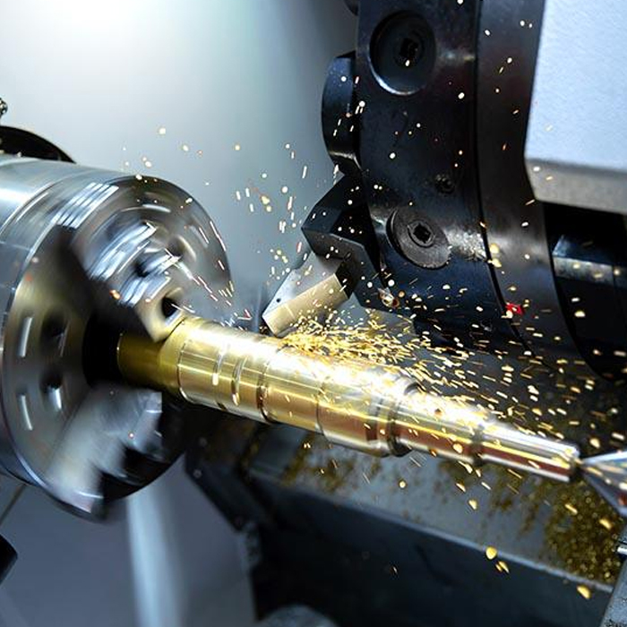
Types of 3-Axis CNC Milling Machines
3-axis CNC mills split roughly into vertical and horizontal spindle orientations. Vertical machining centers position the spindle perpendicular to the worktable. The vertical cnc machining center mv1270, for instance, allows operators to see the tool engage the workpiece directly—useful when machining pockets or intricate profiles. Horizontal machining centers, in contrast, orient the spindle parallel to the table surface. Chips fall away by gravity, improving surface finishes during heavy hogging. Gantry-style 3-axis machines move the entire bridge over a stationary table, accommodating large plates for aerospace tooling. Fixed-column versus moving-column designs also affect floor space and rigidity. Bench-top 3-axis machines serve training labs and light prototyping, while production-grade machines cast from Meehanite iron damp vibrations and hold tolerance under continuous cutting loads.
Key Features of 3-Axis CNC Equipment
Modern 3-axis CNC equipment integrates rigid casting frames, precision linear guideways, and high-speed spindles. MAKCNC fits 10,000–15,000 RPM direct-drive spindles on its vertical milling centers; oil-air lubrication keeps bearings below 45°C even at peak speed. Double-nut ballscrews with backlash under 0.003 mm enable tight bidirectional positioning. Controls from Fanuc or Siemens offer conversational programming for shop-floor edits. Automatic tool changers housing 24 to 32 tools cut setup idle time. Chip augers, washdown systems, and full enclosures contain debris and coolant. Features like tool life monitoring, spindle temperature compensation, and rigid tapping cycle help maintain part consistency across shifts without constant operator intervention.
Applications of 3-Axis Machining
3-axis machining covers a wide material range—aluminum, stainless steel, titanium, engineered plastics. Communication enclosures, consumer electronic housings, and automotive brackets rely on three-axis milling for flatness and hole pattern accuracy. In aerospace, aluminum 7075 ribs and titanium engine mounts are roughed and finished on 3-axis vertical machining centers because the part is often oversized for a 5-axis machine. Oilfield equipment manufacturers use 3-axis horizontal mills to produce valve bodies and flanges. Global cnc machinery cases of makcnc show examples in agricultural machinery, mineral processing components, and hydraulic manifold machining. Job shops often dedicate one 3-axis machine to secondary operations—drilling cross-holes, facing surfaces, and chamfering—after lathe work.
Factors Affecting 3-Axis CNC Machine Price
Price swings based on work envelope, spindle power, control system brand, and optional automation. A basic 3-axis vertical machining center with an 850 mm X-axis travel, a 10,000 RPM spindle, and a Fanuc 0i-MF control may land around US$45,000–60,000. Adding linear glass scales, 15,000 RPM, through-spindle coolant, and a chip conveyor can push the price past US$100,000. The choice of servo motors, ballscrew grade, and casting inspection certificates also matters. Machines sold as part of a customized cnc machines and machining centers from makcnc package often include turnkey tooling and fixturing, which raises upfront cost but reduces integration time. Shipping, import duties, and local service support further influence the final landed cost.
3 Axis CNC Machine Setup Guide

Step 1 Securing the Workpiece
Clamp the raw stock in a vise with ground jaws or bolt it directly to the table using T-nuts and step clamps. We’ve measured parallelism deviations cut in half after switching to hardened and ground vices versus standard mill vices. Verify flatness with a dial indicator—run the indicator across the top face and adjust shims until the needle moves less than 0.01 mm. For thin wall parts, use vacuum chucks or magnetic tables to avoid distortion. Tighten bolts gradually in a star pattern. When using soft jaws, machine the gripping profile on the same setup to ensure concentricity. Secure all loose hoses and cable carriers so they clear the spindle travel envelope. Confirm the fixture does not block coolant nozzles.
Step 2 Tool Selection and Installation
Pick the right tool material and geometry for your material. For aluminum, 3-flute carbide end mills with a 45° helix clear chips fast. Steel demands 4-flute or variable helix tools with TiAlN coating. Insert the tool holder into the spindle taper after cleaning both surfaces with a lint-free wipe. Pull stud torque matters—over-tightening distorts the drawbar; under-tightening risks tool pullout. Measure tool length and diameter offsets with a tool presetter or by touching off. Input data into the control’s tool offset table. Set diameter wear offsets to zero initially. Arrange tools in the magazine according to operation sequence. Pre-stage large face mills adjacent to empty pockets so the automatic tool changer does not collide during rotation.
Step 3 Setting the Work Coordinate System
Establish part zero using an edge finder, 3D sensor, or touch probe. Touch the X and Y faces and record the machine coordinates. For Z zero, bring the tool tip to the top of the workpiece or a 1-2-3 block, listening for the paper drag “tick.” Input these values into the G54–G59 work offset registers. Activate the CNC machine setup offsets by calling G54 in the program header. Run a quick verification: command G00 X0 Y0 in MDI mode and check that the spindle is centered over the reference corner. For multiple vises on the table, set G55, G56, etc., so operators can run duplicate parts without reprogramming. Store offset backups on a USB drive or network folder.
Step 4 Program Loading and First Part Inspection
Load the G-code program via RS-232, Ethernet, or USB. Perform a dry run with the Z axis raised 50 mm above the part to confirm no collision. Slow the rapid traverse to 25% and single-block through the first operation. Watch the distance-to-go display. After machining the first part, stop and measure critical dimensions—hole diameters with a bore gauge, flatness with a surface plate and height gauge. Record values in a first-article inspection report. Adjust tool wear offsets to bring features into the tolerance middle band. With the verification complete, increase feeds to 100% and begin production. Keep a log of tool life and part measurements to catch drift early.
About MAKCNC as a 3-Axis CNC Machine Supplier
MAKCNC manufactures a full range of CNC lathes, vertical and horizontal machining centers, and gantry mills. Our factory team assembles and inspects each 3-axis CNC equipment unit before shipment, running a 48-hour continuous test cycle with laser calibration reports. We ship directly from our ISO-certified factory to ports worldwide. Our engineering group helps customers match the right spindle power, table size, and automation options. For buyers who need high quality and durable cnc lathe solutions alongside milling machines, we offer bundled packages with shared service support. Technical documentation includes setup checklists, maintenance schedules, and recommended spare parts lists. If you are looking for a 3-axis CNC machine supplier, contact us for the latest pricing and a detailed specification sheet.
FAQ of 3-Axis CNC Machine
How to set up a 3-axis CNC machine?
Setting up a 3-axis CNC machine begins with securely clamping the workpiece, then loading the appropriate cutting tools and carefully measuring their offsets. Next, the work coordinate system (typically G54) must be established using an edge finder or probe to define the part zero point. After these mechanical steps, the G-code program is loaded into the control, and a dry run at elevated Z height is performed to verify clearances. The first article is machined, inspected, and necessary wear offset adjustments are entered. Finally, all safety guards are closed and the production run can begin.
What tooling is needed for 3-axis CNC machining?
Essential tooling for 3-axis CNC machining includes a range of carbide end mills (square, ball nose, and corner radius), face mills, spot drills, twist drills, reamers, and taps. The tool holders might be ER collet chucks, hydraulic holders, or shrink-fit systems depending on required runout precision. A tool presetter outside the machine saves valuable spindle downtime. The selection depends on the material; for example, aluminum calls for polished flutes and specific helix angles to avoid built-up edge, while stainless steel requires robust tools with high-temperature coatings. Vise, clamps, parallels, and a granite surface plate with height gauge round out the basic setup.
How to improve 3-axis CNC machine accuracy?
Improving accuracy requires a combination of maintenance, environment control, and proper fixturing. Ballbar tests and laser interferometer calibration should be performed every six months to map and compensate for geometric errors. The machine should sit on an isolated concrete foundation to dampen floor vibrations. Using precision ground vices and minimizing tool overhang reduce deflection. Temperature swings in the shop cause thermal expansion; many high-end shops keep ambient temperature within ±2°C. Regular checks of coolant concentration and chip removal prevent recutting, which degrades surface finish and dimensional stability. Daily warm-up cycles also help bring the spindle and ballscrews to operating temperature before machining.