Optimizing Your Production with a CNC Slant Bed Lathe for Shaft Parts
What is a CNC Slant Bed Lathe for Shaft Parts?
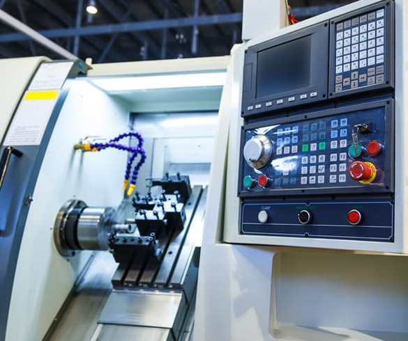
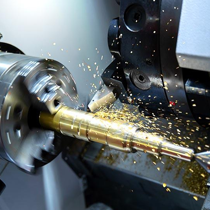
A CNC Slant Bed Lathe for Shaft Parts is a specialized machine tool designed for the high-precision turning of long, slender workpieces like axles, driveshafts, and hydraulic cylinder rods. Unlike traditional flat-bed lathes, its cutting tool and turret are mounted on a bed that is angled, typically at 30, 45, or 60 degrees. This slanted design provides superior rigidity and allows gravity to assist in efficient chip removal, preventing buildups that can mar the surface finish or interfere with the cutting process. For businesses that require tight tolerances and excellent surface quality on cylindrical components, this machine architecture is essential for achieving consistent and repeatable results.
Types of CNC Lathes for Shaft Machining
When selecting a CNC lathe for shaft production, the primary choice is between a slant bed and a flat bed design. While both can turn cylindrical parts, their suitability differs significantly for demanding shaft applications. A flat bed lathe offers easy operator access and is often simpler in construction. However, a slant bed lathe provides distinct advantages for precision shaft work. The angled construction creates a more direct path for cutting forces to travel into the machine's base, significantly reducing vibration and improving dimensional accuracy. This inherent stability is critical when machining long workpieces that are prone to deflection. Furthermore, the efficient chip evacuation of a slant bed design is not just a convenience; it is a quality-control feature that prevents hot chips from causing thermal distortion in the workpiece or damaging the guideways.
Key Features for High-Precision Shaft Turning
Achieving micron-level accuracy on long shafts depends on the machine's fundamental construction and the integration of its components. Several key features directly contribute to the performance of a CNC slant bed lathe for this purpose. At MAKCNC, we focus on a foundation of stability and precision engineering.
- Machine Body Construction: The machine base and major structural components are made from high-strength cast iron, specifically using resin sand casting methods. This material offers excellent vibration damping properties. After casting, the components undergo a thermal aging treatment to relieve internal stresses, ensuring long-term dimensional stability and sustained accuracy.
- Core Drive Components: Precision is dictated by the quality of the motion system. We utilize high-precision ball screws and linear guideways sourced from established manufacturers in Taiwan and Germany. These components ensure smooth, backlash-free movement, which is essential for achieving fine surface finishes.
- Advanced Control System Integration: For applications in demanding sectors like mold making, our machines incorporate intelligent system features. Technologies like feed-forward control and quadrant glitch compensation actively correct for potential errors during tool path changes, effectively addressing common surface defects such as over-cutting marks, quadrant lines, and chatter marks.
- Versatile Machining Capability: The ability to perform multiple operations in a single clamping is a major efficiency driver. Our lathes are designed to complete multi-face machining processes without needing to re-fixture the part, reducing setup time and minimizing the risk of cumulative errors.
Common Applications in Manufacturing
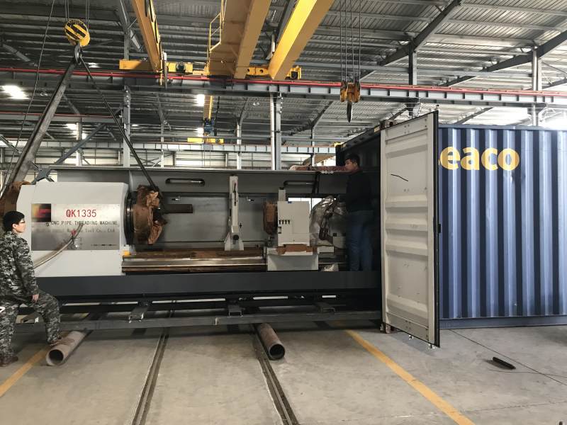
The unique capabilities of a slant bed lathe make it indispensable across several industries where shaft components are fundamental. In the automotive sector, these machines are used to produce crankshafts, camshafts, and transmission shafts, where surface finish and geometric accuracy are directly tied to engine performance and longevity. The aerospace industry relies on them for manufacturing actuator rods and landing gear components, where material strength and failure resistance are non-negotiable. In general industrial manufacturing, applications include motor shafts, hydraulic piston rods, and precision spindles for other machinery. The ability to hold tight tolerances over long lengths makes this machine a cornerstone of modern mechanical production.
Factors Influencing CNC Lathe Price
The investment in a CNC lathe is influenced by several configuration choices and machine specifications. Understanding these factors helps in selecting a machine that meets technical requirements without exceeding budget. The final price is a direct reflection of the machine's capability and features.
| Factor | Description | Impact on Price |
|---|---|---|
| Max Turning Length & Diameter | The physical size of the machine, determining the largest workpiece it can accommodate. | High (Larger machines require more material, larger motors, and a more robust frame.) |
| Spindle Power & Speed | The horsepower and maximum RPM of the main spindle, which dictates material removal rates. | Medium (Higher power and speed require more advanced spindle and drive technology.) |
| Control System | The brand and model of the CNC controller (e.g., Fanuc, Siemens). | Medium (Advanced controllers with more features and processing power are more expensive.) |
| Ancillary Equipment | Options such as programmable tailstocks, steady rests, chip conveyors, and high-pressure coolant systems. | Variable (Each option adds to the base cost of the machine.) |
A Practical Guide to Setting Up for Long Shafts
Incorrect setup is the primary cause of poor results when turning long, slender shafts. Deflection, chatter, and tapering are common problems that can be avoided with a methodical approach. This workflow focuses on providing support and managing cutting forces to maintain straightness and accuracy.
Step-by-Step Setup Procedure for Shaft Turning
-
Tailstock Alignment and Clamping Force: The tailstock's role is to support the free end of the shaft and counteract cutting forces.
- Action: Use a dial test indicator mounted on the tool turret to check the professional cnc machining center solution's tailstock quill for axial and radial alignment with the main spindle's centerline. Adjust as necessary.
- Checkpoint: The indicator reading should be as close to zero as possible when swept across the quill's face and diameter.
- Common Mistake: Applying excessive tailstock pressure. This can bow the workpiece, causing it to be turned with a "barrel" shape. Use just enough force to secure the part without inducing stress.
-
Selection and Positioning of Steady Rests: For shafts with a high length-to-diameter ratio (typically >10:1), a steady rest is needed to prevent the workpiece from deflecting away from the tool.
- Action: Choose a steady rest type (e.g., manual, hydraulic, with rollers or solid pads) based on the required surface finish and material. Position it at the midpoint or at points of maximum potential deflection.
- Checkpoint: Ensure the steady rest supports the shaft without lifting or pushing it off-center. The clamping pressure should be firm but not restrictive.
- Common Mistake: Placing the steady rest on a rough or out-of-round surface. Always turn a small, true "spot" for the steady rest jaws to ride on before engaging them.
-
Sequencing Roughing and Finishing Passes: The cutting strategy must balance material removal with stress management to prevent the shaft from warping.
- Action (Roughing): Divide the turning into multiple sections. Machine one section, then machine a corresponding section from the opposite end to balance the stresses induced in the material. This alternating approach helps maintain straightness.
- Action (Finishing): Perform the final finishing pass in a single, continuous motion from one end of the shaft to the other. This ensures a consistent diameter and avoids "witness marks" where passes might otherwise overlap.
- Common Mistake: Taking a heavy roughing pass over the full length in one direction. This releases uneven internal stresses in the material, almost guaranteeing the shaft will bend.
MAKCNC: Your Supplier for CNC Turning Solutions
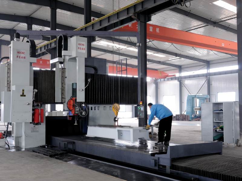
Established in 2016, MAKCNC operates an ISO9001:2015-certified facility dedicated to building reliable and precise CNC machinery. We understand that every production environment has unique needs, which is why we have no rigid minimum order quantity; you can procure a single machine or multiple units. Purchasing in volume can provide access to more favorable commercial terms regarding price, delivery, and service. Our commitment to quality is built into every high quality and durable cnc lathe, from the aged cast iron frame to the German and Taiwanese drive components. Our mature after-sales network ensures support is available when you need it, with a standard commitment to respond within 8 hours and be on-site within 48 hours to address any issues.
Frequently Asked Questions
What is the typical lead time for a new machine?
Our standard lead time ranges from one to six months, depending on the machine's complexity, current order volume, and any requested customizations.
Do you have a minimum order quantity (MOQ)?
We do not enforce a strict MOQ. Single-unit purchases are welcome. However, we do offer improved commercial terms for bulk orders, which can benefit customers in terms of pricing, delivery priority, or after-sales service packages.
What kind of warranty and after-sales support is provided?
All machines come with a standard 12-month warranty after final acceptance. We also provide lifetime paid technical service. For certain tender projects, extended warranties of up to three years can be arranged. Our support team commits to an 8-hour response time and 48-hour on-site arrival for troubleshooting.
If you are sourcing a supplier for high-precision shaft turning solutions, contact our technical team to discuss your project requirements and receive a detailed quotation.