How a CNC Lathing Machine Turns Bar Stock Into Parts
What Is a CNC Lathing Machine
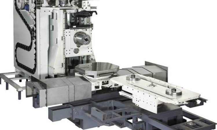
CNC Lathing Machine is a machine tool that holds a workpiece in a chuck or collet, rotates it with a spindle, and moves a cutting tool against the rotating material to create round or rotational features. The CNC portion means computer numerical control, where programmed commands control spindle movement, tool travel, feed motion, and machining sequence. In a typical bar-stock job, a straight metal bar is clamped, faced, turned to diameter, drilled, bored, threaded, grooved, parted off, or otherwise shaped into a finished component. A CNC Lathing Machine is best suited to parts whose primary geometry is cylindrical, such as shafts, bushings, pins, sleeves, threaded fittings, and flanges. It is not the first choice for parts dominated by flat faces, deep pockets, or complex prismatic features; those parts may require a machining center instead.
Types of CNC Lathing Machines
Buyers should first separate machine types by the way they hold material and support the required turning process. A CNC Lathing Machine with a chuck is generally selected for shorter blanks, castings, forgings, or pre-cut bar sections. A bar-fed setup is more suitable when repeat production starts from long stock and the machine repeatedly advances material through the spindle. Flat-bed designs can suit certain general turning tasks, while an CNC inclined bed lathe places the bed at an angle to help chip flow and operator access. The correct type depends on part geometry, batch size, loading method, and required secondary operations. Do not select a machine only because it has more axes or tooling positions. Extra functions add value only when the drawing requires them.
| Machine Arrangement | Best-Fit Work | Buyer Benefit | When It May Not Fit |
|---|---|---|---|
| Chuck-held lathe | Short blanks, forgings, and castings | Flexible for varied workpiece forms | Less efficient when long bar stock must run repeatedly |
| Bar-fed lathe | Repeated turned parts from straight bar | Reduces manual blank loading between cycles | Not ideal for irregular raw material shapes |
| Inclined-bed machine | Production work needing practical chip evacuation | Supports a cleaner working area around the cutting zone | Must still be matched to work envelope and tooling needs |
| Lathe with live tooling | Parts needing turned and selected milled features | Can reduce handling between operations | Not necessary for parts containing only turning features |
Features That Affect Finished Part Quality
A CNC Lathing Machine does not create quality parts through programming alone. The machine structure, workholding, drive components, tooling, and setup process all affect the result. MAKCNC states that many machine bodies use high-strength cast iron, including resin-sand castings, followed by aging treatment to support long-term rigidity and accuracy retention. Core motion components may use high-precision components from Taiwan or Germany. For mold-industry precision work, advanced system integration can include intelligent feedforward and quadrant-jump compensation to address issues such as overcut marks, quadrant marks, and chatter patterns. These features are relevant when a buyer needs stable contouring and repeatable finishing. They do not remove the need for correct tool geometry, sound clamping, suitable cutting conditions, and inspection of the first part.
- Choose rigid workholding when the part projects far from the chuck. The reason is that unsupported material can deflect during cutting. This suits slender shafts, but it may not be necessary for short, stiff workpieces.
- Match insert geometry to the material and operation. A roughing insert and a finishing insert serve different purposes. One tool cannot automatically provide both high stock removal and the desired surface result.
- Review chip control before approving the cycle. Long chips can interfere with the tool and finished surface. Chip behavior changes with material, insert style, feed, and coolant conditions.
How Spindle Rotation Tool Paths Chucking and Feed Motion Shape Bar Stock
The working principle of a CNC Lathing Machine becomes clearer when each motion is connected to a physical result on the part. The spindle rotates the bar. The chuck or collet transfers spindle torque into the material and holds its datum position. Tool paths tell the cutting edge where to move, while feed motion determines how the edge progresses along or across the rotating surface. Together, these actions convert a round bar into a sequence of diameters, shoulders, holes, grooves, tapers, threads, and cut-off parts. A CNC Lathing Machine is effective because it coordinates these movements repeatedly from the same programmed instructions. Yet the process is sensitive to setup errors. A poor clamp, incorrect tool offset, or unsuitable feed can damage a part even when the program logic is correct.
| Process Element | What It Does in Practice | What Happens When It Is Wrong | Actionable Check |
|---|---|---|---|
| Spindle rotation | Creates the circular cutting motion needed for turning | An unsuitable speed can cause poor finish, excess heat, or unstable cutting | Set speed for the work material, diameter, insert, and operation |
| Chucking or collet clamping | Centers and holds bar stock while transmitting rotation | Insufficient or uneven grip can allow movement, runout, or a damaged workpiece | Confirm jaw condition, clamping contact, bar projection, and safe gripping length |
| Tool path | Defines the route used to face, turn, drill, groove, or thread | A wrong path can remove material from the wrong location or leave an unfinished feature | Simulate the program and verify tool offsets before production |
| Longitudinal feed | Moves the tool parallel to the spindle axis for external diameters and turning lengths | An unsuitable feed may leave poor finish or overload the cutting edge | Use a feed appropriate to the finish target and insert recommendation |
| Cross feed | Moves the tool toward or away from the centerline to control diameter and facing | A setup error changes finished diameter or face position | Inspect the first part and correct offsets before continuing the batch |
A practical sequence starts with bar loading and clamping. The machine faces the bar end to establish a clean reference surface, then turns the outside diameter by moving the tool along the spindle axis. A drill can enter the centerline for an internal feature. A boring tool can enlarge or finish that hole. Grooving and threading tools follow dedicated programmed paths, and a parting tool separates the finished component from the remaining stock. This sequence suits rotational parts. It does not replace milling when the drawing contains multiple off-center pockets, broad flat surfaces, or complex non-round geometry.
CNC Lathing Machine Applications for Bar Stock Parts
A CNC Lathing Machine is commonly considered when the drawing contains concentric diameters, bores, threads, grooves, tapers, or axial holes. Typical part families include hydraulic fittings, threaded adapters, motor shafts, bearing sleeves, bushings, collars, pins, valve components, and cylindrical connectors. The best application is not defined only by the product name. Buyers should review the raw material form and the full operation sequence. If the part begins as round bar and most features share the same centerline, turning is usually the logical primary process. If the part needs several faces machined in one clamping, a professional CNC machining center solution may be more appropriate, or may be used after turning. This choice reduces unnecessary handling, but it must be based on the actual drawing rather than assumptions about the industry.
- Use turning as the primary process for rotational parts. This fits bar stock with concentric features. It does not fit parts where milling features dominate cycle time.
- Plan secondary operations before selecting the machine. Cross holes, flats, and keyways may require live tooling or a separate machining process. The limit is that not every secondary feature justifies a more complex lathe.
- Review the intended batch pattern. Repeated small parts can benefit from bar feeding, while mixed low-volume work may favor flexible manual loading and faster setup changes.
CNC Lathing Machine Price Factors
The purchase price of a CNC Lathing Machine varies because the delivered configuration is not identical from one requirement to another. Buyers should request a quotation based on the part drawing, raw-stock form, workholding method, control requirement, tooling scope, automation need, and destination service arrangement. A basic machine for straightforward external turning will not have the same price structure as a CNC Lathing Machine requiring additional axes, live tooling, a bar feeder interface, specialized fixtures, or customized functions. Freight, packaging, commissioning support, spare-part planning, and requested warranty terms can also affect the commercial package. MAKCNC states that there is no mandatory minimum order quantity, so a single machine can be purchased. Multi-machine procurement may receive improved commercial terms related to price, delivery, or after-sales service, but those terms should be confirmed in the quotation rather than assumed.
| Price Driver | Why It Changes the Quote | When to Include It |
|---|---|---|
| Machine size and work envelope | Larger work capacity changes structural and component requirements | Include when the part diameter, length, or chucking demand requires it |
| Tooling and turret arrangement | More tooling capability can reduce handling but increases configuration cost | Include when the drawing needs several operations in one cycle |
| Automation equipment | Bar feeding or loading equipment changes the production arrangement | Include for repeated production, not automatically for occasional batches |
| Customized equipment | Special fixtures or process requirements need engineering review | Include when standard workholding cannot hold the part safely |
CNC Lathing Machine User Guide for First Part Approval
Before running production, first-time users should treat setup as a controlled verification task rather than a simple loading step. Start by reviewing the drawing and identifying every turned feature, datum surface, thread, groove, hole, and tolerance requirement. Confirm that the bar diameter and material match the programmed process. Install the correct jaws or collet, set a safe bar projection, and check clamping before spindle rotation. Load each tool and establish its offset according to the machine procedure. Then simulate the program, run the first part at a controlled proving condition, and inspect the resulting dimensions and surfaces before repeating the cycle. A CNC Lathing Machine can repeat an approved process efficiently, but it cannot correct an unverified setup by itself. This method suits both new buyers and experienced shops introducing a new part number. It is less relevant only when a qualified team has already validated an unchanged recurring setup.
- Check the drawing and raw bar. Verify material form, starting diameter, finished features, and inspection points.
- Set workholding. Confirm the chuck or collet grips evenly and that the workpiece is supported appropriately.
- Set tools and offsets. Identify roughing, finishing, drilling, boring, grooving, threading, and parting tools as required.
- Prove the program. Check tool paths for clearance around jaws, stock, tailstock support, and finished features.
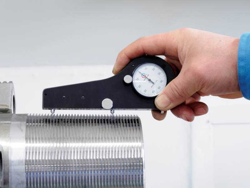
- Inspect the first component. Compare actual dimensions and surface condition with the drawing before batch production.
- Record approved settings. Save tool data, jaw arrangement, material details, and inspection results for repeat work.
FAQ of CNC Lathing Machine Selection
Can a CNC Lathing Machine make parts from long bar stock?
Yes, provided the machine and production setup are arranged for the required bar size, support method, and loading approach. Long stock may be manually loaded or handled through a bar-feeding arrangement. The selection should consider the actual part length, stock form, batch pattern, and safety requirements.
What is the difference between turning and milling?
Turning normally rotates the workpiece while the cutting tool moves to create rotational features. Milling normally rotates the cutting tool while the workpiece is held in position or moved along machine axes. A CNC Lathing Machine is generally preferred for round, concentric forms; a machining center is more suitable for many non-round features.
Can one setup complete every part?
Not always. Some parts can be completed in one clamping when their required features match the machine configuration. Other parts need a second operation, alternative workholding, or milling equipment. The drawing decides this point, not the general machine category.
CNC Lathing Machine Supplier for Practical Manufacturing Requirements
MAKCNC supplies CNC lathing equipment, CNC machining centers, and customized machine solutions for buyers reviewing manufacturing requirements before machine selection. Established in 2016, the company reports multiple production lines and sample-machine inventory. MAKCNC lists S09001:2015 in its company information and states an ordering lead time of 1 to 6 months, depending on the project arrangement. Standard warranty coverage is typically 12 months after machine acceptance, followed by lifetime paid service; some tender projects may require different warranty terms. The after-sales network is stated to respond within 8 hours and arrive on site within 48 hours for fault handling where applicable. Learn more about MAKCNC when comparing a CNC Lathing Machine supplier, machine configuration, and service requirements. If you are sourcing a CNC Lathing Machine, contact MAKCNC with your drawings to request the latest quotation and selection advice.