
A Linear Guide Vertical Machining Center Differs From Box Ways
What Is a Linear Guide Vertical Machining Center?
Linear Guide Vertical Machining Center refers to a vertical CNC machine whose moving axes run on linear guideways rather than sliding box ways. A linear guide uses recirculating rolling elements between the rail and carriage, reducing sliding resistance during axis movement. In practical machining terms, this design often favors quick axis changes, efficient positioning moves, and lighter cutting loads. A box-way machine uses broad sliding contact surfaces, usually with lubrication, to support moving components. The buyer’s question is not which guideway is universally better. The correct question is whether the machine’s guideway behavior matches the part material, tooling, cutting style, and production mix. A Linear Guide Vertical Machining Center is often a sound fit for parts with many holes, pockets, contours, and frequent non-cutting moves. It may not be the first choice when the workload is dominated by heavy interrupted cuts on large, difficult materials.
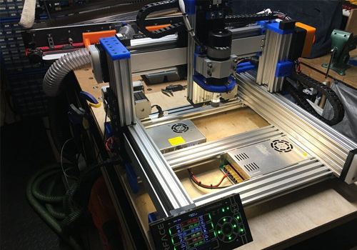
Types of Guideway Configurations
A Linear Guide Vertical Machining Center is not one fixed machine category. Buyers should identify the guideway arrangement before comparing quotations because linear guideways may use ball-type or roller-type carriages, while box-way designs may vary in contact area, lubrication arrangement, and structural mass. Ball linear guides generally prioritize low resistance and responsive movement. Roller linear guides are commonly selected when a linear-guide design needs greater support stiffness than a ball-based arrangement. Box ways emphasize sliding contact and damping, which can suit force-heavy operations. The practical conclusion is simple: select a guideway type by cutting behavior, not by a single brochure phrase. Choose a linear-guide configuration when cycle time depends on frequent positioning, contouring, drilling patterns, and tool changes. Consider box ways when deep cuts, interrupted cutting, and sustained load matter more than quick axis reversal. Neither approach removes the need to assess spindle output, machine structure, tooling, workholding, and control settings together.
- Ball linear guides: Usually suited to responsive axis movement and general high-mix machining. They are less suitable when buyers expect them to replace a heavy-duty sliding-way structure without checking the actual cutting load.
- Roller linear guides: A potential middle ground where a buyer wants linear motion characteristics with stronger carriage support. Verify the machine builder’s axis design rather than assuming every roller guide has the same behavior.
- Box ways: Often considered for damping-focused, force-heavy milling. They may be less attractive where short positioning moves and frequent acceleration dominate the cycle.
Comparison: a spec-led table connecting guideway type to acceleration, load capacity, damping, and suitable cutting conditions.
The guideway choice affects more than a catalog specification. It changes how the machine reacts when the cutter enters material, reverses direction, or moves across a long non-cutting distance. A Linear Guide Vertical Machining Center generally has lower moving friction than a sliding-way machine, so it can be well suited to programs with repeated positioning moves. Box ways generally provide more damping through their sliding contact, which can help when the machine sees high cutting forces or unstable interrupted cuts. Getting this decision wrong has a direct shop-floor effect. A machine selected only for fast motion may disappoint during heavy roughing. Conversely, a machine chosen only for damping may add non-cutting time to a program built around dense drilling and pocketing operations.
| Guideway type | Acceleration behavior | Load capacity behavior | Damping behavior | Suitable cutting conditions | Risk if selected incorrectly |
|---|---|---|---|---|---|
| Ball linear guideways | Usually favorable for responsive starts, stops, and axis reversals | Must be reviewed against the actual part, fixture, and cutting-force demand | Lower inherent damping than a broad sliding-way design | Drilling patterns, finish milling, pocketing, contouring, and parts with frequent positioning moves | Heavy interrupted milling can expose vibration or stability limits if the full machine design is not matched to the cut |
| Roller linear guideways | Responsive motion with stronger guide support than typical ball-guide arrangements | Often considered where the buyer needs a more load-oriented linear guideway option | Moderate, depending on the complete structure and carriage design | Mixed production that needs efficient positioning and meaningful cutting support | Assuming roller guides alone guarantee heavy-cut performance ignores spindle, casting, fixture, and tool limits |
| Box ways | Usually less focused on quick axis response than rolling-guide designs | Commonly favored for sustained load-oriented machining | Higher damping potential from sliding contact surfaces | Heavy roughing, difficult materials, interrupted cuts, and work where stability has priority | Using box ways for a high-volume drilling or short-cycle part can increase non-cutting time without adding useful value |
Features That Matter Beyond the Guideway Label
A Linear Guide Vertical Machining Center should be evaluated as a complete mechanical and control system. Guideways influence motion, but they do not work alone. The machine body, screw system, spindle, control functions, toolholding, and workholding determine the final cutting result. MAKCNC machine structures commonly use high-strength cast iron, including resin-sand castings, with aging treatment intended to support long-term accuracy and rigidity. Core transmission parts such as ball screws and guideways may use high-precision components from Taiwan or Germany. For mold-related high-accuracy work, advanced system integration can include intelligent feedforward and quadrant-jump compensation to address issues such as overcut marks, quadrant marks, and chatter-related surface patterns. This is relevant when the application involves circular interpolation or changing directions. It does not mean a compensation setting can correct weak fixturing, worn tooling, unsuitable feeds, or a poor part setup.
- Choose structural mass and damping first when roughing force and interrupted cutting dominate. The reason is that a stable cutting platform matters more than quick empty travel in this scenario.
- Choose responsive motion first when the program contains repeated holes, pockets, contours, and short positioning moves. The limit is that fast motion does not replace appropriate cutting support.
- Review control compensation for mold and contouring work. It can help manage direction-change errors, but it must be validated using the buyer’s own test part and machining process.
Applications and Part Families
A Linear Guide Vertical Machining Center is commonly considered for general precision machining where varied parts move through the shop in smaller batches. Suitable part families can include plates, housings, mold components, fixture elements, and prismatic parts requiring drilling, tapping, pockets, and multi-face machining after appropriate setup planning. For multi-variety, small-batch production, the ability to complete multiple faces in one clamping can reduce handling and datum-transfer risk. The recommendation fits buyers whose production schedule changes often and whose parts have a large share of positioning and feature machining. It does not automatically fit a shop milling one demanding roughing operation for most of each cycle. In that case, compare actual depth of cut, tool diameter, material condition, fixture stiffness, and spindle load behavior against a box-way alternative. A useful early-stage test is to separate programmed time into cutting time and non-cutting time. If non-cutting movement is a large share, linear guideway behavior deserves closer attention.
Linear Guide Vertical Machining Center Price Factors
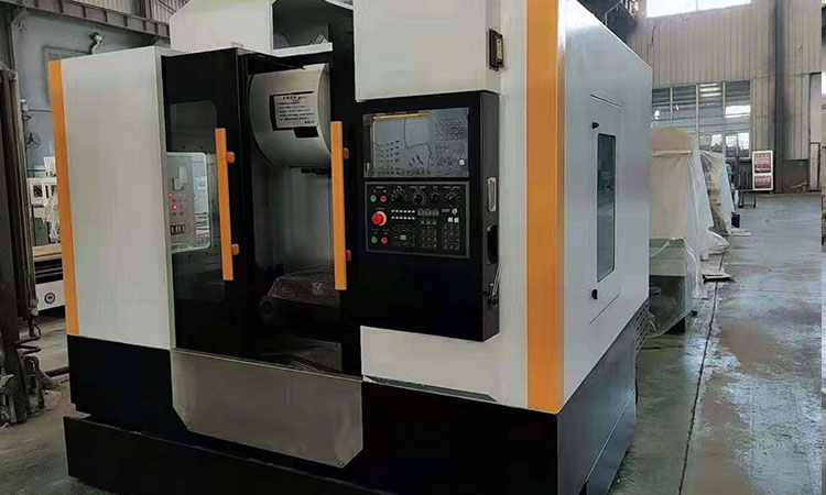
The price of a Linear Guide Vertical Machining Center varies because guideway type is only one component of the configured machine. Buyers should avoid comparing quotations based on table size or travel alone. The more useful comparison is a line-by-line review of the mechanical structure, guideway arrangement, spindle configuration, control system, toolchanger scope, coolant options, workholding needs, export packing, commissioning support, and warranty terms. MAKCNC can supply a single machine without a hard minimum order quantity, while multi-machine purchases may receive improved commercial terms on price, delivery, or after-sales support. Manufacturing lead time is generally stated as 1 to 6 months, so delivery planning should be matched to the requested configuration and production schedule. A lower initial quotation may not be the lower project cost if it omits required options or cannot support the intended workpiece and tooling process.
| Quotation factor | What the buyer should request | Why it affects total cost |
|---|---|---|
| Guideway configuration | State whether the workload favors responsive positioning, heavy roughing, or a mixed process | The wrong guideway priority can create lost cycle time or restricted cutting methods after installation |
| Machine structure | Ask how the casting and aging process support the selected configuration | Structure affects stability, surface finish potential, and long-term operating behavior |
| Control functions | Identify contouring, mold, or direction-change accuracy needs before quoting | Compensation and control requirements may differ by part family |
| Service scope | Confirm acceptance, warranty, and paid lifetime service terms in the contract | Standard warranty is typically 12 months after complete-machine acceptance, while project terms can differ |
Linear Guide Vertical Machining Center User Guide
Before shortlisting a Linear Guide Vertical Machining Center, create a test-part brief rather than sending only a general request for a VMC quotation. Start with the material, largest workpiece, finished features, critical surface areas, annual quantity, fixture concept, cutting tools, and the longest expected operation. Next, identify whether the process is dominated by drilling and positioning, contour milling, finishing, heavy roughing, or interrupted cuts. Then ask the supplier to explain how the proposed guideway type supports that process. This method fits early-stage technical research because it turns a broad machine question into reviewable criteria. Its limit is that paper review cannot replace a verified cutting trial for difficult applications. Where surface marks, chatter, or contour accuracy are sensitive, provide drawings and process details for technical assessment before ordering.
- List the three most common part families and their workpiece materials.
- Mark every operation as positioning-intensive, finishing-intensive, or force-intensive.
- Identify the heaviest fixture and the most demanding cutting operation.
- Compare linear-guide and box-way proposals against the same part and tooling assumptions.
- Confirm optional functions, acceptance criteria, packing requirements, service terms, and delivery timing in writing.
Linear Guide Vertical Machining Center Supplier Considerations
When selecting a Linear Guide Vertical Machining Center supplier, the buyer should look for a technical discussion centered on the machining process rather than a generic statement that one guideway is superior. MAKCNC was established in 2016 and operates multiple production lines with sample-machine inventory. Its product range includes CNC machining centers, CNC lathing machines, and CNC machines. Buyers assessing a vertical-machine project can review the vertical CNC machining center MV1380 and discuss whether the proposed configuration fits their part and cutting conditions. For special layouts or process requirements, customized CNC machines may be relevant. The right supplier should clearly state what is included, what requires an option, which assumptions support the recommendation, and where a requested application falls outside the machine’s intended scope.
FAQ of Linear Guide Vertical Machining Center Selection
Is a Linear Guide Vertical Machining Center always faster than a box-way VMC?
No. A Linear Guide Vertical Machining Center can favor responsive axis movement and efficient positioning, but finished cycle time depends on the entire program. If roughing consumes most of the cycle, spindle behavior, tool engagement, structure, and damping may matter more than travel motion. Compare the same part program rather than relying on one general speed claim.
Should mold machining always use linear guideways?
No. Mold work includes very different operations, from finishing contours to heavy stock removal. A Linear Guide Vertical Machining Center can be suitable for precision contouring and frequent directional changes when its structure, control functions, tooling, and fixtures fit the task. Heavy roughing requirements still need a separate stability review.
What information should be included in an RFQ?
Provide part drawings, material, workpiece mass, fixture concept, key operations, target production quantity, required surface areas, local power conditions, and delivery destination. This lets the supplier assess whether a Linear Guide Vertical Machining Center or a box-way design better matches the planned machining method.
If you are looking for a CNC machining center supplier, contact MAKCNC for the latest quotation and guideway selection advice based on your drawings.