
How to Choose CNC Machine Tools for Mechanical Parts
What Are CNC Machine Tools for Mechanical Parts
CNC Machine Tools for Mechanical Parts are computer-controlled machines and tooling systems used to remove material, form features, and achieve required dimensions on components such as shafts, housings, brackets, flanges, plates, and mold-related parts. The correct choice is not simply a choice between a lathe and a machining center. It starts with the part drawing. Production planners should identify the workpiece material, overall form, turning features, milled faces, hole types, surface requirements, and tolerance callouts before selecting equipment. CNC Machine Tools for Mechanical Parts should match the dominant process rather than the most visually obvious feature. A round shaft with keyways, for example, may begin on a CNC lathe and require secondary milling. A prismatic gearbox housing may need a machining center with stable multi-face access. For early-stage mechanical part machining, the practical goal is to reduce re-clamping, avoid unnecessary transfers, and choose tooling that can maintain a repeatable process. This decision affects fixture design, programming time, inspection workload, and future capacity planning.
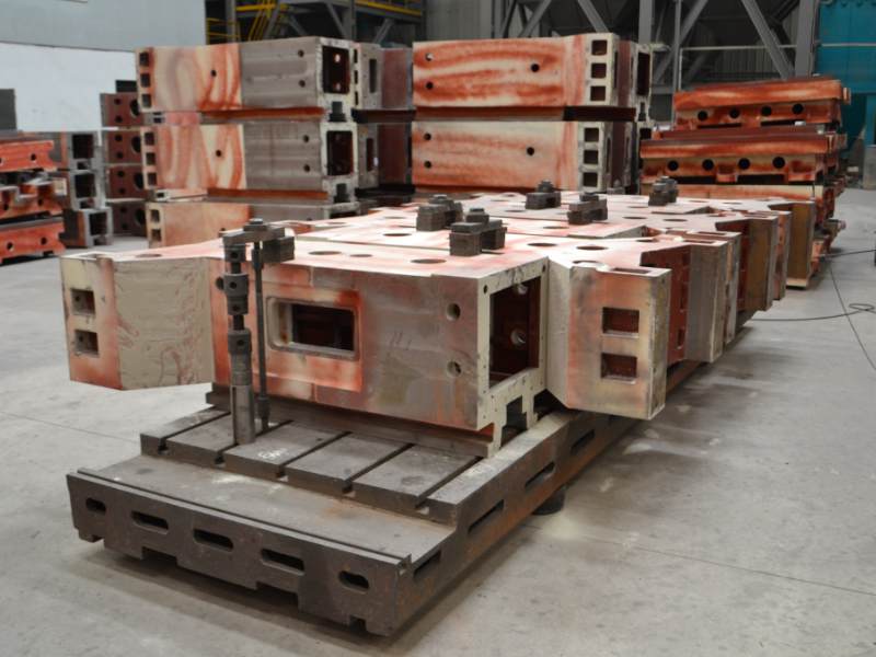
Types of CNC Machine Tools for Mechanical Parts
There are several machine categories used in mechanical part machining, and each suits a different part family. CNC Machine Tools for Mechanical Parts should be selected according to whether the part is mainly rotational, mainly prismatic, or mixed in form. A CNC lathing machine is usually the direct choice for shafts, sleeves, threaded parts, flanges, and other workpieces defined by diameters and axial features. A vertical machining center is commonly selected for plates, brackets, covers, and housings with accessible top-side features. A horizontal machining center can suit parts that require machining on several faces where fixture access and chip evacuation influence process planning. When a part combines turning and milling operations, planners should compare separate-operation routing with a special machine configuration or a custom process arrangement. The best option is the one that reduces handling without making tooling access difficult.
| Machine Type | Best-Fit Part Features | Selection Reason | When It May Not Fit |
|---|---|---|---|
| CNC lathing machine | Diameters, tapers, threads, grooves, bores | Supports rotational part geometry and turning tool paths | Not the first choice when many faces need milling and drilling |
| Vertical machining center | Flat faces, pockets, holes, profiles, top-access features | Suitable for common prismatic workpieces and fixture-based machining | May require re-clamping for multiple side faces |
| Horizontal machining center | Multi-face housings, side holes, internal cavities | Can improve access to several faces in one process plan | May not be justified for simple one-face workpieces |
| Customized equipment | Special part forms or repeated dedicated processes | Matches a defined production route and fixture requirement | Not suitable before the part design and demand pattern are stable |
For rotational components, review the cnc lathing machine range before deciding whether separate milling operations are required. For prismatic components with pockets, bores, and machined mounting faces, a professional cnc machining center solution gives planners a clearer basis for evaluating vertical and horizontal configurations.
Features That Matter During CNC Machine Tool Selection
CNC Machine Tools for Mechanical Parts need a machine structure, transmission system, and control capability that support the planned process. Start by checking rigidity, workholding access, tool reach, and the ability to complete related features in a controlled sequence. MAKCNC machine bodies commonly use high-strength cast iron, including resin-sand castings, with aging treatment intended to support long-term accuracy and rigidity. Core motion components such as ball screws and guideways may use high-accuracy components from Taiwan or Germany, selected as part of the whole-machine system. For mold-related work and parts with demanding finish requirements, advanced control integration can include intelligent feedforward and quadrant-jump compensation to help address overcut marks, quadrant marks, and vibration patterns. These features fit processes where contour transitions and directional changes affect finish quality. They do not replace correct fixturing, suitable feeds, a stable toolholder, or a verified program.
- Choose rigidity first when the part has deep cavities, interrupted cuts, or long tool overhangs. A rigid machine and fixture help reduce vibration, but they cannot correct a weak workholding plan.
- Choose multi-face capability when the drawing requires related features on several surfaces. One-clamping multi-face machining can reduce datum transfer risk, but only when all needed faces remain accessible.
- Choose control functions for contour work when mold profiles, circular interpolation, or directional changes influence visible surfaces. These functions are less relevant for simple rough turning work.
- Choose tooling access before spindle preference when internal pockets or angled features are involved. A capable machine cannot compensate for a tool that cannot reach the feature safely.
Mechanical Part Applications and Process Planning
CNC Machine Tools for Mechanical Parts are used for parts that must fit into assemblies, transmit motion, seal against mating surfaces, support loads, or locate other components. Typical applications include shafts with bearing seats, flanges with bolt circles, motor brackets, valve bodies, machine covers, fixture plates, bearing housings, and mold-related inserts. The practical planning rule is simple: assign each feature to the process that creates it with the least avoidable error. Turning should handle concentric diameters and axial bores when the part is rotational. Milling should handle faces, slots, pockets, and profiles. Drilling and boring should be planned according to hole depth, entry condition, and tolerance requirement. CNC Machine Tools for Mechanical Parts should also be reviewed against the inspection plan. If a feature must be measured from a specific datum, that datum should be established and protected throughout the route. A process that creates good individual dimensions can still fail if positional relationships between features are not controlled.
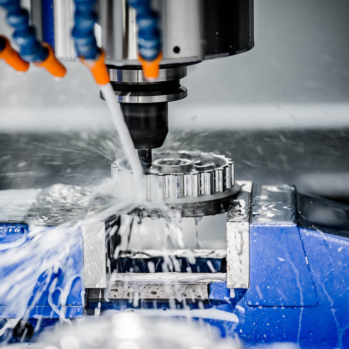
Map Material Geometry and Tolerances to the Right Tools
Action: map part material, feature geometry, and tolerance requirements to suitable milling, drilling, turning, and finishing tools. This is the most useful step in CNC machine tool selection because machine capability and CNC cutting tools must work together. Start with the drawing rather than the tool catalog. CNC Machine Tools for Mechanical Parts can only deliver the intended result when the cutter material, tool geometry, holder, workholding, and machining sequence suit the workpiece. For example, a steel shaft with critical diameters needs turning tools selected for stable diameter control, while a steel bracket with threaded holes needs milling cutters, drills, and thread-making tools planned around the hole location and access direction. Tool selection should be documented feature by feature so purchasing, programming, and quality teams use the same assumptions.
| Part Requirement | Suitable Tool Direction | Key Checkpoint | Common Failure Reason |
|---|---|---|---|
| Steel outside diameter or bore | Turning insert and boring tool | Confirm tool rigidity and bore access | Long overhang causes chatter or taper |
| Flat face, pocket, or shoulder | End mill or face mill | Match cutter reach to wall depth | Tool deflection leaves poor wall finish |
| Hole with location requirement | Spotting tool, drill, boring tool, or reamer | Define whether size, location, or finish is the main requirement | Using one drilling step for a feature that needs finishing |
| Threaded feature | Threading insert, tap, or thread mill | Check access and material behavior before choosing the method | Tool choice ignores blind-hole or interrupted-thread conditions |
| Final surface or edge condition | Finishing tool, chamfer tool, or deburring process | Set final operation after heavy material removal | Finishing is performed before later clamping marks occur |
Step-by-Step Tool Mapping Procedure
- Classify the material. Identify whether the drawing specifies steel, cast iron, aluminum, stainless material, or another workpiece material. This determines the starting direction for machining tool materials and insert geometry.
- Separate the features. List every turned diameter, bore, pocket, face, hole, thread, slot, chamfer, and contour. Do not select one general cutter before this feature list exists.
- Mark tolerance-driving features. Highlight dimensions that control fit, location, concentricity, or surface condition. These features usually require a planned finishing operation rather than a roughing tool path.
- Choose the operation order. Rough machine first, establish datums, perform semi-finishing where needed, then finish the features that depend on stable references.
- Check tool reach and holder clearance. Review walls, adjacent features, fixture clamps, and internal cavities. A theoretically suitable cutter fails when the holder contacts the workpiece or fixture.
- Validate the first part. Measure the tolerance-driving features before releasing the route for repeat production. If the result is unstable, review fixturing and tool extension before changing machine settings.
For the long-tail question, which CNC tools machine steel parts accurately, the answer depends on the feature. Carbide cutting tools are commonly considered for steel milling and turning because they can support stable cutting when the machine, holder, and workholding are properly matched. High-speed steel tools can remain relevant for certain drilling and special-form applications. Ceramic tooling may suit selected high-temperature machining conditions, but it is not a universal replacement because interruption, setup stability, and part geometry matter. CNC Machine Tools for Mechanical Parts should therefore be specified with the intended machining tool materials and holder system, not as an isolated equipment purchase.
CNC Machine Tools for Mechanical Parts Price Factors
The price of CNC Machine Tools for Mechanical Parts changes with machine type, working configuration, control options, workholding requirements, tooling scope, inspection expectations, shipping arrangements, and after-sales terms. A buyer should request quotations based on the actual drawing package and expected process instead of comparing only a base machine price. A low initial figure may exclude fixtures, toolholders, tooling, commissioning support, or options required for the target part. Conversely, a higher-configured machine may be unnecessary when the workpiece has simple geometry and limited feature requirements. MAKCNC supports single-machine purchasing without a hard minimum order quantity, while multi-machine purchases may receive better commercial terms in price, delivery, or after-sales service. Delivery planning should also account for the stated lead-time range of one to six months, depending on the selected machine and commercial arrangement.
| Price Influence | Buyer Question | Reason to Check |
|---|---|---|
| Machine configuration | Does the selected configuration match the drawing features? | A configuration mismatch can create secondary operations or unused cost. |
| Tooling package | Are CNC cutting tools and holders included or separately sourced? | Tooling directly affects readiness for first-part production. |
| Fixtures and clamping | Does the quote include workholding designed for the part? | Part stability often depends on fixture planning. |
| Delivery and support | What is included in shipment, installation support, and service? | Commercial scope should be clear before purchase approval. |
User Guide for First-Part Machining
CNC Machine Tools for Mechanical Parts should be introduced through a controlled first-part process rather than moving directly to full production. Begin by confirming that the released drawing includes material, dimensions, tolerances, datum references, thread information, surface requirements, and revision status. Next, prepare the fixture plan and make sure clamping does not cover machining areas or distort thin sections. Load the correct tools and verify tool identification against the programmed operations. Then dry-run the program with safe clearances, review tool paths around clamps and walls, and machine a first part under controlled conditions. Inspect the dimensions that drive assembly fit before continuing with the remaining features. If variation appears, identify whether it comes from workholding, tool wear, tool reach, datum selection, thermal condition, or program logic. Do not treat every dimensional issue as a machine issue. CNC Machine Tools for Mechanical Parts perform best when the complete process is checked as one system.
- Do not skip datum review. A wrong reference surface can move every later feature, even if each tool path is programmed correctly.
- Do not finish before roughing is stable. Finish tools should not be asked to correct vibration marks created by an unsuitable roughing setup.
- Do not ignore chip control. Chip accumulation can affect surface quality, tool life, and access to internal features.
- Do not release production after visual inspection alone. Measure the features that determine assembly performance and document the first-part result.
FAQ of CNC Machine Tools for Mechanical Parts
How do you choose CNC machine tools for mechanical parts?
To choose CNC Machine Tools for Mechanical Parts, begin with the part family and process route. Select a CNC lathe for rotational features such as diameters, grooves, threads, and bores. Select a machining center for prismatic faces, pockets, slots, drilled holes, and profiles. Then check whether the part needs multiple face operations, whether one-clamping machining is beneficial, and whether the planned tools can reach every feature. The limit is that machine category alone does not ensure a good process. Tooling, fixturing, programmed sequence, and inspection references must support the same part requirements.
Which CNC tools machine steel parts accurately?
Steel parts can be machined with turning inserts, carbide end mills, drills, boring tools, reamers, thread tools, and finishing tools chosen for the specific feature. Accuracy depends on more than the tool material. A short, stable tool assembly, suitable holder, secure clamping, controlled cutting conditions, and a finishing pass where needed are also required. Carbide tooling is often selected for steel applications, but the correct choice changes with the steel grade, interruption, hole depth, feature accessibility, and required finish. CNC Machine Tools for Mechanical Parts should be evaluated together with this tooling plan.
What tools are used for precision mechanical components?
Precision mechanical components may require face mills, end mills, ball-nose tools, drills, boring tools, reamers, turning inserts, grooving tools, threading tools, chamfer tools, and deburring tools. The final tool list should come from the feature map, not from a standard package. A bore may need drilling followed by boring or reaming. A profile may need rough milling followed by a finishing cutter. A shaft may need rough turning, finish turning, grooving, and threading. The right method depends on the drawing and inspection criteria.
MAKCNC as a CNC Machine Tools for Mechanical Parts Supplier
MAKCNC has manufactured CNC equipment since 2016 and offers CNC lathing machines, CNC machining centers, and CNC machines for mechanical part machining planning. The company operates multiple production lines and maintains sample machine inventory. Its service terms typically include a twelve-month warranty after whole-machine acceptance and lifetime paid service, while some tender projects may require longer free warranty conditions. A mature after-sales network may provide response within eight hours and on-site fault handling within forty-eight hours. Buyers evaluating CNC Machine Tools for Mechanical Parts can also review the vertical cnc machining center mv1380 for milling-based work or discuss customized cnc machines when the part route requires a dedicated arrangement.
If you are sourcing CNC Machine Tools for Mechanical Parts, submit your part drawings to MAKCNC for current equipment and tooling selection advice.