
Flat Bed CNC Lathe Turning and Threading Workflows
Flat Bed CNC Lathe Definition
A Flat Bed CNC Lathe is a computer-controlled turning machine with horizontal guideways and a flat bed supporting the carriage, cross slide, tailstock, and workholding equipment. It removes material from a rotating workpiece using single-point cutting tools, drills, boring bars, grooving tools, and other cutters. These machines are widely used to produce shafts, sleeves, pipe components, flanges, bushings, and other rotational parts. Unlike a manual lathe, the CNC control manages spindle speed, feed rate, axis movement, tool changes, and thread cycles through a programmed sequence. For international manufacturers, this layout provides a useful combination of rigidity, open working space, familiar operation, and repeatable production results.
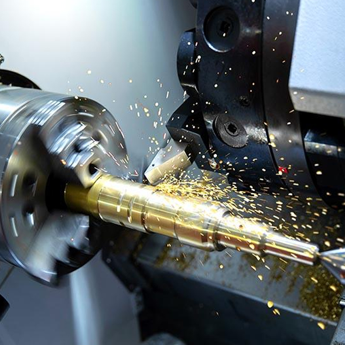
Types of Flat Bed CNC Lathes
Several machine designs fall within the flat bed turning category. A standard two-axis model controls the X and Z axes and is suitable for outside diameter turning, facing, grooving, drilling, and routine threading. Machines with a larger swing and longer distance between centers are intended for heavy shafts, pipe sections, and extended workpieces. Depending on the application, a machine may include a hydraulic chuck, programmable tailstock, steady rest, automatic tool changer, or live tooling option. A flat bed CNC turning machine can also be configured for pipe machining, oilfield work, or high-volume automotive production. When comparing CNC equipment with a manual flat bed lathe, buyers should weigh production volume, repeatability requirements, available operator skills, and the need to store proven programs. Manual lathes remain valuable for repair work and one-off parts, while CNC models reduce repeated measuring and manual handwheel adjustments.
Features of a Flat Bed CNC Lathe
The defining feature of this machine is the direct support provided by its flat bed and guideways. A properly sized bed helps control vibration while cutting steel, cast iron, and large-diameter alloy components. Spindle power, chuck size, maximum swing, turning diameter, distance between centers, and Z-axis travel establish the machine’s usable working range. The digital CNC control stores part programs and lets the operator call up tool offsets, work coordinates, spindle commands, and threading cycles as needed. Many MAKCNC configurations are designed for high speed, high rigidity, high performance, and high efficiency in industrial production. Still, the best choice depends on more than machine weight. Available power, shop floor space, chip removal, coolant handling, and tolerance requirements all matter. A heavy-duty model is not necessarily the most practical option for a shop producing mostly small precision bushings.
Flat Bed CNC Lathe Application
Flat bed turning equipment is used across communication equipment, consumer electronics support parts, automotive production, aerospace components, minerals processing, agricultural machinery, chemical equipment, petroleum service, water conservancy, and geological exploration. Common workpieces include threaded connectors, hydraulic cylinders, pump shafts, bearing seats, pipe adapters, rollers, valve bodies, and transmission components. In oilfield service, a machine may be configured for large pipe diameters and long threaded sections, provided the chuck, spindle bore, drive motor, and tool system are matched to the part. Production managers often combine roughing and finishing on the same machine when a component can be completed in a single setup. For parts requiring more extensive milling, MAKCNC also supplies a professional CNC machining center solution covering vertical and horizontal CNC machine center equipment.
Turning Workflow From Stock Preparation to Inspection
A dependable turning cycle starts before the workpiece is loaded into the chuck. The operator reviews the material certificate, stock diameter, finished dimensions, drawing revision, and required machining allowance. The bar or blank is then cut to a length that allows adequate chuck engagement and safe tool clearance. Once mounted, the chuck jaws are tightened evenly, runout is checked with a dial indicator, and a tailstock or steady rest is added for long workpieces. Next, the operator establishes the work coordinate, measures tool geometry, and confirms the insert grade. Roughing removes most of the stock at an appropriate depth of cut and feed rate. Semi-finishing leaves a controlled allowance, and the finishing pass brings the part to its specified diameter and surface quality. Final inspection may include micrometer readings, thread gauges, bore gauges, and visual checks for burrs, chatter, or poor chip control.
Workholding and Tool Selection
Three-jaw chucks are practical for round stock and regular production runs. Four-jaw independent chucks offer greater control when machining eccentric, square, or irregular workpieces. Collets are well suited to smaller bar stock where low runout is important, while faceplates and custom fixtures can support unusual components. Tooling should be selected for the operation, not simply based on what is already installed in the turret. A CNMG-style insert may be used for rough turning steel, while a sharper finishing insert is better for light cuts and improved surface finish. Boring bars handle internal diameters, and grooving tools need sufficient clearance for the required width and depth. For aluminum, a sharp polished insert can reduce built-up edge. Hardened steel requires more careful selection of insert grade and cutting data. In production, even a capable machine can perform poorly when paired with an unsuitable tool holder or an insert that does not manage heat effectively.
CNC Lathe Threading Workflow
CNC lathe threading usually begins with a turned major diameter for an external thread or a prepared bore for an internal thread. The programmer identifies the thread standard, nominal size, pitch, thread length, runout, chamfer, and material condition. The control then applies a threading cycle, such as a commonly supported G76 or G92 format, depending on the control brand and machine configuration. The tool must be aligned correctly on the spindle centerline, and the insert included angle must match the required thread form. The first pass removes a controlled amount of material. Subsequent passes reduce the load until the tool reaches the programmed depth. A spring pass may help clean up a small amount of remaining material at the crest or flank. Thread inspection should be completed with a calibrated ring gauge, plug gauge, thread micrometer, or matching mating part. Cutting fluid, chip control, and a properly formed thread relief are particularly important for long or deep threads.
How Does a Flat Bed CNC Lathe Perform Threading
A flat bed CNC lathe performs threading by synchronizing Z-axis feed with spindle rotation. The spindle encoder reports position to the CNC control, which moves the threading tool at a feed equal to the specified thread pitch. For example, when cutting a 2.0 mm pitch, the tool advances 2.0 mm along the Z axis during every spindle revolution. The operator enters the thread diameter, depth, lead angle, start point, end point, and pass information into the program. Rather than cutting to full depth in one movement, the machine produces the thread over several passes. Before beginning production, the operator should verify spindle direction, tool orientation, clearance, thread relief, and first-piece dimensions. A test cut on scrap stock can reveal an incorrect pitch, reversed tool direction, or unsuitable depth schedule before valuable material is machined.
CNC Turning Operations and Programming Checks
Common CNC turning operations include facing, external turning, internal turning, taper turning, chamfering, grooving, parting, drilling, boring, and threading. Programs generally begin with a safe startup line, work coordinate selection, spindle command, tool call, coolant command, and approach movement. The programmer should allow safe clearance around the chuck, jaws, tailstock, and fixtures. Tool nose radius compensation may be necessary where profile accuracy is critical, particularly on tapers, radii, and blended contours. Feed per revolution is often preferred in turning because it maintains a consistent relationship between feed and spindle speed. The program should also include a controlled retract and a clear end-of-cycle position. For a new component, a dry run, single-block mode, reduced rapid override, and simulation check are sensible precautions. These steps help protect the insert, chuck jaws, fixture, and machine structure.
What Materials Can a Flat Bed CNC Lathe Machine
A flat bed CNC lathe machine can process carbon steel, stainless steel, alloy steel, cast iron, aluminum, brass, bronze, copper, plastics, and selected nickel-based alloys when machine power and tooling are matched correctly. Material hardness, thermal conductivity, work-hardening tendency, and chip shape all influence cutting conditions. Aluminum often allows higher spindle speeds, but it requires sharp tools and reliable chip evacuation. Stainless steel can generate considerable heat and may work-harden if the tool rubs rather than cuts. Cast iron produces abrasive dust, making suitable insert grades and enclosure protection important. Plastics need sharp cutting geometry, moderate heat control, and enough support to prevent deformation. Titanium and nickel alloys demand careful planning of speed, feed, tool engagement, and coolant delivery. Before scheduling difficult materials, manufacturers should review spindle torque, chuck pressure, guideway condition, and coolant capacity.
Flat Bed CNC Lathe Price Factors
The price of a flat bed CNC lathe varies according to its working envelope, spindle specification, control system, bed length, motor power, chuck type, tooling package, and automation level. A compact two-axis machine for small shafts will not have the same cost as a large-bore oilfield model built for pipe threading. Hydraulic chucks, steady rests, chip conveyors, bar feeders, programmable tailstocks, and measuring systems can also affect the final quotation. When requesting a price, buyers should provide the largest diameter, maximum part length, material types, thread standards, monthly output, tolerance targets, and available electrical supply. Shipping destination, export packing, installation assistance, operator training, spare parts, and warranty terms may influence the landed cost as well. MAKCNC can discuss customized CNC machines and machining centers from MAKCNC when a standard configuration does not fit the intended production process.
Flat Bed CNC Lathe User Guide
Before starting a cycle, inspect lubrication levels, hydraulic pressure, coolant condition, chuck clamping, tool seating, and guard operation. Confirm that the workpiece is properly supported and that no tool, tailstock component, or fixture can strike the chuck. Set the work offset from a known reference, measure every changed tool, and review the program against the drawing. For the first piece, use a conservative rapid override and watch spindle load, vibration, chip formation, and surface finish. Long stringy chips should never be removed by hand while the spindle is running; use a chip hook or stop the machine first. At the end of the shift, clean the bed and chuck area, remove chips from guideway covers, and record unusual noise, vibration, or temperature. Operators should follow the machine maker’s electrical, lubrication, lifting, and lockout instructions instead of relying on informal shop adjustments.
How to Set Up a Flat Bed CNC Lathe for Turning
To set up a flat bed CNC lathe for turning, first review the drawing and select stock with enough allowance for facing and diameter reduction. Mount the workpiece with sufficient jaw contact, check runout, and install a tailstock center when the length-to-diameter ratio requires additional support. Load the roughing, finishing, drilling, boring, or grooving tools in their planned stations. Touch off each tool or enter measured geometry into the control, then set the work zero at the selected face or datum. Program a safe approach, roughing passes, finishing pass, and retract position. Run the program in graphics or dry-run mode, then make the first cut with reduced overrides. Measure the first part and adjust wear offsets in small increments. Once dimensions and surface finish are stable, record the proven setup so another qualified operator can repeat it accurately.
Flat Bed CNC Lathe Supplier
MAKCNC is a professional flat bed CNC lathe supplier and manufacturer serving industrial buyers, distributors, engineering companies, and production plants. Our product range includes CNC lathing machines, CNC machining centers, and CNC machines for turning and milling requirements. Recommended products include CNC machining center series, CNC oilfield lathes, and manual oilfield lathes, with configurations suited to communication, automotive, aerospace, petroleum, agricultural machinery, chemical, mineral, and geological applications. Buyers can review the company background through about MAKCNC and see equipment delivered in different markets through the company’s global case information. If you need a flat bed CNC lathe supplier, contact MAKCNC for the latest product quotation, technical configuration, export details, and application advice.
FAQ of Flat Bed CNC Lathe
How does a flat bed CNC lathe perform threading
It performs threading by linking spindle rotation with synchronized Z-axis movement. The encoder tracks spindle position, and the CNC control advances the threading tool according to the programmed pitch. The operator sets the thread diameter, pitch, length, depth, pass count, tool position, and retract path. Several passes gradually form the finished thread profile. A correctly prepared diameter, aligned insert, suitable relief groove, stable workholding, and reliable chip control are all required. The first thread should be checked with the appropriate gauge before the machine runs a larger batch.
What materials can a flat bed CNC lathe machine
It can machine carbon steel, stainless steel, alloy steel, cast iron, aluminum, brass, bronze, copper, engineering plastics, and selected difficult alloys. The practical limit depends on spindle torque, cutting tool grade, workholding, coolant capacity, and the required tolerance. Material hardness and heat behavior determine the suitable speed and feed range. With stainless steel, the tool must maintain a positive cutting action to avoid work hardening. Aluminum benefits from sharp tools and efficient chip evacuation. Buyers should provide material grades and part drawings so the machine and tooling can be matched correctly.
How to set up a flat bed CNC lathe for turning
Prepare the stock, clamp it securely, check runout, install the required tools, measure tool offsets, and set the work coordinate. Review the programmed spindle speed, feed, depth of cut, clearance, and cutting direction. Complete a simulation or dry run, then machine a first piece at a controlled override. Measure critical diameters, lengths, bores, and threads, then adjust wear offsets only after confirming the measurement method. The approved setup should be documented with the tool list, insert details, work offset, chuck pressure, and inspection results.
Choose MAKCNC for Your Turning Project
A well-configured flat bed CNC lathe combines dependable workholding, repeatable turning, accurate threading, and practical maintenance in one production platform. The right choice begins with the part drawing and process requirements, not only the advertised spindle speed. MAKCNC can help international manufacturers compare machine size, spindle bore, chuck arrangement, control functions, tooling, automation, and export support. If you are looking for a flat bed CNC lathe supplier, please contact MAKCNC to obtain the latest product quotation and discuss a suitable CNC lathing machine or CNC machining center for your factory.