How to Master Feeds and Speeds on a High Speed CNC Turning Machine
The primary challenge in high-speed turning is balancing cycle time with thermal control. Pushing for faster output can generate excessive heat at the cutting edge, leading to premature tool wear, poor surface finish, and dimensional inaccuracies. A high speed CNC turning machine is designed for this demanding environment, but its performance depends entirely on the operator's ability to manage the relationship between cutting parameters. Understanding how to set feeds, speeds, and depth of cut to evacuate heat effectively is the key to unlocking both speed and precision.
This is not about a single magic number. It is a systematic process of balancing interlocking variables. The goal is to direct thermal energy away from the workpiece and the cutting insert, primarily by forming a chip that carries the heat with it. When parameters are correct, the machine, tool, and workpiece remain thermally stable, ensuring consistent quality across long production runs.
A Systematic Method for CNC Thermal Control in Turning
Controlling heat is an active process. Instead of relying on a single chart, use this five-step method to find the optimal parameters for your specific material, insert, and machine. This approach balances the five key elements: surface speed, feed per revolution, depth of cut, coolant delivery, and insert grade.
- Establish a Baseline with Manufacturer Data: Always begin with the cutting tool manufacturer's recommendations. They provide a starting surface speed (SFM or m/min) and feed per revolution (IPR or mm/rev) for the specific insert grade and workpiece material. This is your safe, proven starting point, not the final optimized value.
- Define the Depth of Cut (DOC): The DOC significantly influences cutting forces and heat generation. For roughing passes, a larger DOC combined with a higher feed rate is effective. For finishing, a much smaller DOC is used with a potentially higher surface speed to achieve the desired finish. Do not vary the DOC during a single pass if possible, as this can cause thermal shock to the insert.
- Optimize Coolant Delivery: Coolant must do more than just wet the part; it must reach the precise point of friction between the insert and the workpiece. High-pressure coolant is excellent for breaking chips and flushing them from the cutting zone. Ensure nozzles are aimed correctly to penetrate the steam barrier that can form at high temperatures. The volume and pressure of the coolant are just as important as its presence.
- Execute a Test Cut and Analyze the Chip: Run a short program and observe the chip. The chip is the best indicator of cutting health. Ideal chips are well-formed, consistent in shape, and typically have a straw or light brown color, indicating appropriate heat levels. They should break cleanly and not wrap around the part or tool.
- Adjust Parameters Systematically: Based on the test cut, make one adjustment at a time. Use the following table as a guide for troubleshooting common issues related to CNC thermal control.
Troubleshooting Guide for Turning Parameters
| Observation / Problem | Primary Cause | Recommended Action |
|---|---|---|
| Blue or Dark Purple Chips | Excessive heat. Surface speed is too high for the material and feed rate. | Reduce surface speed (RPM) by 10-15%. If the problem persists, slightly increase the feed per revolution to create a thicker chip that carries more heat away. |
| Built-Up Edge (BUE) on Insert | Workpiece material is welding to the tool. Surface speed is too low. | Increase surface speed by 10-15%. Consider an insert with a slicker coating (e.g., TiN or AlTiN). |
| Poor Surface Finish / Chatter Marks | Vibration. Could be caused by excessive tool stick-out, incorrect feed, or a non-rigid machine structure. | First, ensure the tool is as short as possible. Then, try increasing the feed per revolution to put more pressure on the cut and stabilize it. If chatter persists, check machine rigidity. |
| Rapid Insert Wear or Chipping | Feed rate is too high for the insert geometry, or the insert grade is too brittle. | Reduce the feed per revolution. If chipping continues, switch to a tougher (less hard) carbide grade or an insert with a stronger cutting edge preparation. |
Key Machine Characteristics that Impact High-Speed Performance
The success of high-speed turning isn't just about programming. The physical construction of the high speed CNC turning machine itself sets the upper limit on performance. A machine that lacks rigidity or precision in its core components will fail to hold tolerances, regardless of the parameters used.
Rigidity and Thermal Stability
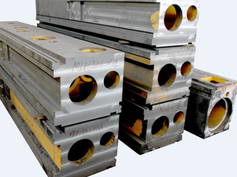
High cutting forces and thermal expansion are constant enemies of precision. Our machines are built on a foundation of high-strength cast iron, often using resin sand casting for superior structural integrity. This heavy, well-ribbed base provides exceptional vibration damping. After casting, the frames undergo a lengthy aging treatment. This process relieves internal stresses in the metal, ensuring that the machine's geometry remains stable and accurate over years of thermal cycling and heavy use. A machine that can't absorb vibration will produce chatter, and one that deforms with temperature changes will lose its accuracy.
Precision of the Drive System
At high speeds, even microscopic errors in motion are magnified. The components that translate program commands into physical movement—the ball screws and linear guides—are critical. We utilize high-precision components from established manufacturers in Taiwan and Germany. These elements are chosen for their low friction, high load capacity, and minimal backlash, allowing for aggressive acceleration and deceleration without sacrificing positional accuracy. This system-wide approach ensures that the performance of the integrated control system is fully realized at the tool tip.
Common Mistakes in Setting High Speed CNC Turning Feeds
Achieving optimal high speed CNC turning feeds requires avoiding common pitfalls that can undermine even the best equipment. Recognizing these errors is the first step toward building a more reliable and productive process.
- Mistake: Focusing Only on Spindle Speed. Many operators believe "high speed" simply means maxing out the RPM. In reality, surface speed is the critical variable, and it must be balanced with the feed rate. An excessively high speed with too low a feed can cause the tool to rub rather than cut, generating immense frictional heat without efficient material removal.
- Mistake: Ignoring Chip Formation. The chip is your most valuable diagnostic tool. Stringy, bird's-nest chips are not just inconvenient; they indicate poor cutting parameters and can damage the surface finish or wrap around the tool, causing breakage. A properly set feed and depth of cut will produce a chip that breaks cleanly and carries heat away from the cutting zone.
- Mistake: Using the Wrong Tool Geometry. Not all inserts are created equal. An insert designed for heavy roughing has a different edge preparation and chipbreaker geometry than one designed for light finishing. Using the wrong geometry can lead to high cutting forces, poor chip control, and excessive heat, even if the speeds and feeds are theoretically correct for the material.
- Mistake: Poor Workholding Strategy. At high rotational speeds, centrifugal forces become a major factor. Inadequate clamping pressure from the chuck can allow the workpiece to shift, leading to inconsistent dimensions, poor finish, and potentially a dangerous situation. Always verify that your workholding is rated for the planned RPM.
Partnering with a Manufacturer for Long-Term Success
Selecting a high speed CNC turning machine is a significant investment that extends beyond the initial purchase. The right manufacturing partner provides the engineering foundation and support network necessary to ensure long-term productivity and profitability.
As an ISO9001:2015 certified company established in 2016, MAKCNC builds machines designed for sustained accuracy. Our engineering philosophy emphasizes system synergy, where high-quality components like German or Taiwanese drive systems are integrated into rigid, stress-relieved cast iron frames. This ensures the entire machine works in concert to deliver optimal performance. For industries like mold making, our advanced control systems incorporate technologies like intelligent feed-forward and quadrant glitch compensation to solve common high-speed machining issues like over-cutting and chatter marks right at the source.
We understand the needs of global B2B buyers. We have no rigid minimum order quantity—you can procure a single machine. However, batch orders may qualify for improved commercial terms regarding pricing, delivery, or after-sales service. Our standard warranty covers the machine for 12 months after acceptance, with lifetime paid service available. For specific projects or tenders, extended warranties of up to three years can be arranged. Our mature after-sales network is committed to an 8-hour response time, with a technician on-site within 48 hours to address any issues. To learn more, you can read about MAKCNC's professional capabilities.
Frequently Asked Questions about High Speed CNC Turning
How do you calculate feed rate for high speed CNC turning?
The basic formula for machine feed rate, typically measured in inches per minute (IPM) or millimeters per minute (mm/min), is: Feed Rate = Spindle Speed (RPM) x Feed per Revolution (IPR or mm/rev). First, you determine the correct surface speed for your material, which gives you the RPM. Then, you select a starting feed per revolution from your tool supplier's data. Multiplying these two gives you the programmed feed rate.
What feed prevents overheating in CNC turning?
There is no single feed rate that prevents overheating. It is the balance of parameters. A feed rate that is too low can cause rubbing and friction, increasing heat. A feed rate that is too high can cause tool chipping. The ideal CNC lathe feed rate is one that creates a thick enough chip to carry heat away efficiently without putting excessive stress on the cutting edge, all while being paired with the appropriate surface speed.
How do you set speed and feed on a CNC lathe?
The best practice is a systematic approach. Start with the tool manufacturer's recommended surface speed and feed per revolution for your material. Set your depth of cut. Run a test piece and analyze the chip formation, surface finish, and sound of the cut. Then, make small, incremental adjustments to one variable at a time—either speed or feed—until you achieve the desired result in terms of chip control, tool life, and finish.
If you are evaluating equipment for high-speed turning applications, our technical team can provide a detailed process and machine recommendation. Contact us to discuss your specific production requirements.