
Using a Vertical Machining Center for Mold Making to Improve Surface Finish
A Vertical Machining Center for Mold Making is precision equipment designed to meet the demanding requirements of the mold and die industry. Achieving a mirror-like surface finish directly from the machine, minimizing or eliminating manual polishing, is a primary goal for any competitive mold shop. This is not just about aesthetics; it is about reducing cycle times, lowering labor costs, and ensuring the functional quality of the final molded part. The key to this level of quality lies in understanding how the machine's construction, its control system, and your programming strategies work together.
For shops specializing in high-precision molds, the machine's ability to handle complex geometries without leaving artifacts like "over-cut marks, quadrant marks, or chatter marks" is a direct measure of its value. This article explains how to leverage your VMC's capabilities, particularly through intelligent toolpath generation, to produce superior mold surfaces that require less post-processing. We will cover machine characteristics, specific programming techniques, and factors to consider when selecting a machine for these demanding applications.
Machine Characteristics That Dictate Finish Quality
The final surface finish is a direct result of the machine's mechanical stability and precision. A machine that cannot hold tight tolerances under load will never produce a clean surface, regardless of programming. When evaluating a Vertical Machining Center for Mold Making, focus on the core components that provide a foundation for accuracy.
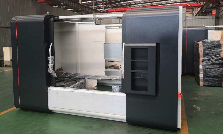
The machine frame is the starting point for all precision. At MAKCNC, our machine bodies are constructed from high-strength cast iron, often using resin sand casting methods. This material provides excellent vibration damping. More importantly, the castings undergo an aging treatment to relieve internal stresses, which ensures the machine maintains its geometric accuracy and rigidity over years of operation. A non-stabilized frame can warp subtly over time, destroying its ability to perform high-tolerance work.
Core drive components are the next critical layer. The ball screws and linear guideways that control axis movement must be of the highest grade. We integrate high-precision components from established brands in Taiwan and Germany, ensuring smooth, backlash-free motion. This directly translates to better surface finishes, especially during complex 3D contouring where axes are constantly changing direction.
Buyer's Checklist for Machine Rigidity and Precision
When assessing a VMC for mold work, use this checklist to look beyond the basic specifications:
- Frame Material and Treatment: Is the frame made from high-grade cast iron (e.g., Meehanite or similar)? Has it undergone a stress-relieving or aging process? Ask the manufacturer for details on their casting and treatment process.
- Drive System Components: Who manufactures the ball screws and linear guideways? Look for reputable names known for precision and longevity.
- Spindle Quality: What is the spindle's runout specification? For mold making, a low runout is essential to prevent tool chatter and improve surface quality.
- Control System Features: Does the CNC controller have high-speed machining functions? Look for features like intelligent look-ahead, which reads blocks of G-code in advance to optimize acceleration and deceleration, preventing jerky movements that mar the surface.
- System Integration: How are these components integrated? A machine with premium parts that are not properly assembled and calibrated will underperform. An ISO9001:2015 certified process, like ours at MAKCNC, ensures a systematic approach to assembly and quality control.
How Toolpaths Reduce Cusp Marks and Polishing Time
Even on the most rigid machine, the programming strategy—the toolpath—is what ultimately creates the surface. For mold cavities, the goal is to minimize the height of the "cusps" or scallops left between adjacent tool passes. Smaller cusps mean less time spent on manual polishing. This is achieved by carefully controlling linking moves, step-over distances, and using rest-machining operations.
Advanced control systems help by incorporating technologies like intelligent feed-forward control and quadrant glitch compensation. These features anticipate and correct for the tiny errors that occur when an axis changes direction, which are the primary cause of witness marks on a finished surface. By combining these system features with smart CAM programming, you can dramatically reduce benchwork.
Here is a breakdown of how to approach these toolpath strategies for a better finish.
Strategies for Minimizing Manual Polishing
| Toolpath Strategy | How It Improves Finish | Key Checkpoints & Common Failures |
|---|---|---|
| Optimizing Linking Moves | Controls how the tool moves between cutting passes. Abrupt, straight-line rapids can cause the machine to jerk, leaving dwell marks. Using smooth, arcing "high-feed" links or ramp-down entries keeps motion fluid and maintains constant tool pressure. | Checkpoint: Review link moves in your CAM software's simulation. Look for sharp changes in direction. Failure: Using default "plunge" or "rapid retract" settings on contoured surfaces. This is a common cause of tool marks at the start and end of a pass. |
| Managing Step-over | The distance the tool moves over between passes. A smaller step-over creates smaller, shallower cusps, resulting in a smoother "as-machined" surface. This is a direct trade-off with cycle time, so finding the right balance is key. | Checkpoint: Calculate the theoretical cusp height based on your tool radius and step-over. Aim for a height that is acceptable for your polishing process. Failure: Using a large step-over (e.g., 50% of tool diameter) for finishing passes. This is suitable for roughing but leaves significant work for polishing. |
| Using Rest-Machining | Also known as "remachining," this strategy uses a smaller tool to clean out corners and details that a larger finishing tool could not reach. It prevents the larger tool from slowing down and "burning" in tight corners and ensures a uniform finish across the entire surface. | Checkpoint: Ensure the rest-machining toolpath blends smoothly with the main finishing path. The engagement and exit points should be tangential. Failure: Not using rest-machining at all, forcing a single large tool to handle the whole surface. This leads to poor corner quality and inconsistent surface finish. |
Key Factors Influencing VMC Cost for Mold Applications
The price of a Vertical Machining Center for Mold Making can vary significantly based on its configuration. Understanding the key cost drivers helps you invest in the capabilities you need without overspending on features that do not add value to your specific operations. While we have no rigid minimum order quantity (MOQ) and can supply a single machine, procuring multiple units often results in better commercial terms on price and delivery.
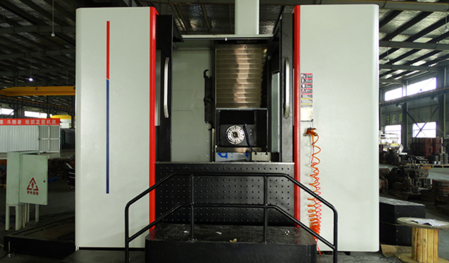
- Axis Configuration: A standard 3-axis VMC is the most common and cost-effective. A 4-axis machine adds a rotary table, and a 5-axis machine provides full simultaneous contouring. For complex molds requiring undercuts, a 5-axis machine can complete the part in a single setup, saving significant time, but comes at a higher initial cost.
- Spindle Speed and Power: Mold making often involves small tools and high rotational speeds for fine finishing. A high-speed spindle (12,000 RPM or higher) is a common requirement and adds to the cost compared to a standard 8,000 RPM spindle.
- Control System: The CNC controller is the brain of the machine. High-end controllers from Fanuc, Siemens, or Mitsubishi with advanced high-speed machining software packages are more expensive but are essential for achieving the finish quality and cycle times required in mold making.
- Tool Changer Capacity: A larger automatic tool changer (ATC) allows for more tools to be staged, enabling more complex jobs to run unattended. A 24-station ATC is standard, but 30- or 40-station options increase the machine's price and versatility.
- Through-Spindle Coolant (TSC): TSC delivers high-pressure coolant through the tool itself, which is very effective for deep pocket milling and drilling. It improves tool life and chip evacuation but is an optional extra on most machines.
Why Partner with an Experienced VMC Supplier
Choosing a machine is only part of the process. Your supplier provides the support and service that keeps your investment profitable. Founded in 2016, MAKCNC has developed multiple production lines and maintains an inventory of machine models to ensure delivery lead times between 1 to 6 months. Our focus is on building reliable, precise machines and backing them with responsive service.
Our standard warranty covers the machine for 12 months after acceptance, with lifetime paid service available. For specific tenders or projects, we can offer extended warranties, such as three years of free coverage. Our mature after-sales network is structured to provide an initial response within 8 hours and have a technician on-site to address any issues within 48 hours.
As a professional CNC machine manufacturer, we understand the pressures of the mold industry. For more information about our company and capabilities, you can learn more about makcnc, a professional cnc lathing machine manufacturer.
If you are looking for a reliable Vertical Machining Center for Mold Making, please contact our team to discuss your specific application and receive a detailed quote.