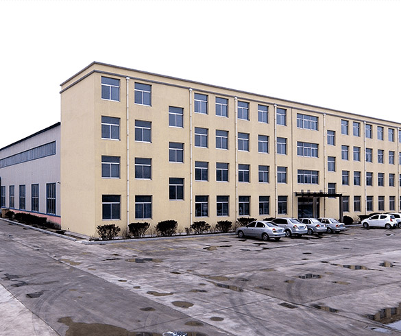
Horizontal Machining How to Reduce Tool Wear
What is Horizontal Machining?
Horizontal machining is a metal-cutting method in which the spindle runs parallel to the shop floor, allowing the cutting tool to approach the workpiece from the side. With this layout, chips can fall away from the cutting zone rather than building up around the tool and finished surface. A horizontal machining center can combine milling, drilling, tapping, boring, and other operations in one programmed setup. For international buyers, spindle speed and table size are only part of the decision. Tool life, cycle time, chip control, surface quality, and maintenance cost all influence the final cost per part. When cutting data, workholding, coolant delivery, and tool geometry match the material, the machine can remove stock consistently while limiting edge breakdown, thermal cracking, built-up edge, and premature insert replacement.
Types of Horizontal Machining Equipment
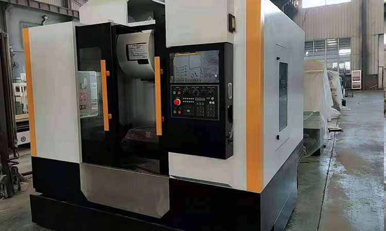
Types of horizontal machining equipment differ by spindle size, pallet arrangement, axis travel, and intended production use. A standard four-axis machine is often suitable for housings, brackets, bearing parts, and general prismatic components. Four-axis and five-axis models can machine several faces of a workpiece with fewer manual setups, helping maintain feature position while reducing handling time. Twin-pallet machines allow operators to load one pallet while the other is cutting, which makes them well suited to repeat production. Some models use an extended bed for large castings, while compact units are common in automotive, pump, valve, and industrial component production. Buyers should compare spindle torque, table load, tool magazine capacity, rapid traverse, axis travel, and coolant filtration instead of selecting a machine by maximum rpm alone. The right specification depends on material, stock removal requirements, part size, batch volume, and the number of faces that need machining.
Features of Horizontal Machining
The main features of horizontal machining include stable workholding, effective chip evacuation, multi-face access, and solid support for long cutting tools. Since the spindle cuts from a horizontal direction, gravity helps move chips away from the cutter and toward the conveyor. This is particularly useful for deep pockets, blind holes, cast iron components, and aluminum parts that produce a high volume of chips. A rigid column, accurately aligned guideways, and a well-supported table help control vibration during heavy cuts. Automatic tool changers also reduce non-cutting time and make it practical to combine roughing, semi-finishing, drilling, and finishing in one cycle. MAKCNC supplies professional CNC machining center solutions for buyers comparing vertical and horizontal equipment. The machine control, spindle taper, toolholder quality, and coolant system should be evaluated as one complete working package.
Horizontal Machining Application
Horizontal machining applications include automotive transmission housings, hydraulic valve bodies, pump cases, engine components, agricultural machinery parts, petroleum equipment, aerospace fittings, and mineral processing components. The arrangement is especially useful when several sides of a casting or billet must be machined accurately. A gearbox housing, for example, may require side bores, mounting faces, oil passages, and bolt holes. Completing these operations with fewer reclamping steps can improve positional accuracy and reduce fixture labor. In aerospace and medical work, the focus may be on controlled heat generation, fine surface finishes, and stable cutting of titanium or stainless steel. In heavy industry, machine selection may instead prioritize torque, large workpiece capacity, and resistance to interrupted cuts. The best horizontal machining process begins with a detailed review of the part drawing, stock condition, tolerances, production quantity, and inspection method.
Horizontal Machining Price and Operating Cost
Horizontal machining price involves more than the initial machine quotation. Spindle power, axis stroke, pallet size, rotary axis options, tool magazine capacity, chip conveyor type, probing, coolant filtration, and automation can all affect the purchase cost. Buyers should also calculate the cost of inserts, holders, coolant, electricity, preventive maintenance, fixtures, operator time, and downtime from tool changes. A lower-priced machine can become costly if it requires frequent manual chip removal or cannot maintain stable cutting data during heavy work. On the other hand, a machine with a higher purchase price may deliver a lower cost per part when it machines multiple faces in one setup and protects tools through better chip control. Ask suppliers for a complete technical offer that includes delivery time, installation support, training, spare parts, warranty terms, and sample machining results.
Horizontal Machining Process and Cutting Parameters
The horizontal machining process should begin with cutting data based on the workpiece material, insert grade, tool diameter, radial engagement, axial depth, and available machine power. Cutting speed that is too high raises temperature and can lead to flank wear, crater wear, or edge softening. Feed that is too low may cause the tool to rub instead of cut, generating heat and leaving a hardened surface. Excessive feed can chip the insert, damage the workpiece, or overload the spindle. Radial engagement matters as well. A full-width cut creates a different heat pattern from a light side cut, even when spindle speed remains the same. During CNC horizontal milling, engineers should make one controlled change at a time and record tool life, spindle load, surface finish, and chip form. This makes it easier to identify a stable cutting window rather than relying on maximum speed alone.
Choose Tool Geometry for the Workpiece Material
Tool selection directly affects edge life. Aluminum usually benefits from sharp, polished flutes that prevent material from adhering to the cutting edge. Cast iron often requires a wear-resistant carbide grade and geometry capable of handling abrasive dust. Stainless steel needs a sharp but well-supported edge, suitable chip breakers, and cutting data that avoids excessive rubbing. Hardened steel may require coated carbide, ceramic, or another tool material selected for the hardness level and finishing allowance. Titanium and nickel alloys demand close heat control because they retain high temperatures near the cutting zone. Tool overhang should be as short as the part permits. Excessive projection increases deflection and vibration, producing uneven wear even when the nominal cutting speed appears acceptable.
Horizontal Machining Operations That Protect Tools
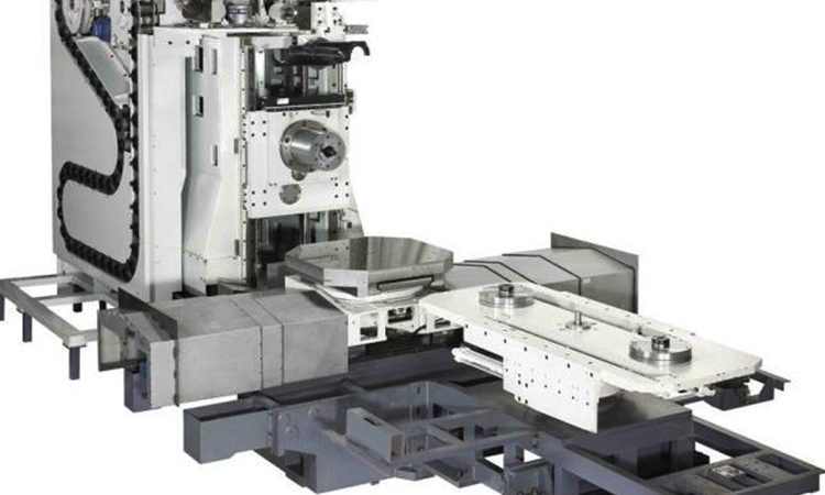
Several horizontal machining operations can be adjusted to extend tool life. Use adaptive or trochoidal paths when deep cavities would otherwise keep the cutter engaged at full width. Enter the material gradually instead of forcing a tool directly into a corner. Leave a consistent finishing allowance after roughing so the finishing tool does not encounter random hard spots or uneven stock. For drilling, use peck cycles only when chip length or hole depth makes them necessary; unnecessary pecking adds cycle time and can create extra heat. Boring bars should be properly supported and kept as short as practical. Tapping requires matched speed, feed, synchronization, and coolant delivery. If the machine has probing, use it to verify tool length and work offset before starting a long batch. A small setup error can result in a damaged insert, a scrap part, and an avoidable stoppage.
Coolant Delivery and Chip Evacuation
Coolant must reach the cutting edge with enough flow and pressure to remove heat and carry chips away. Flood coolant can perform well in common steel and cast iron operations when the nozzle is directed at the actual engagement point. Through-spindle coolant is particularly valuable for deep drilling, deep pockets, and tools that block external flow. Poorly aimed coolant may simply wash chips around the table without properly cooling the tool. Filtration also deserves close attention because fine particles can damage pumps, clog nozzles, and reduce pressure. In a horizontal machine, chips generally fall toward the conveyor, but poor fixture design or excessive chip packing can still cause recutting. Recut chips act like an abrasive load, potentially scratching the finished surface or breaking the tool edge. Clean coolant, suitable concentration, and regular conveyor inspection all support stable production.
How Can Horizontal Machining Reduce Cutting Tool Wear?
How can horizontal machining reduce cutting tool wear? The main advantage comes from the relationship between spindle orientation, chip flow, workholding, and multi-face access. Chips naturally leave the cutting area under gravity, making the tool less likely to recut material that has already been removed. Fewer setups also reduce alignment errors and help keep the same tool path stable across several faces. To achieve these benefits, the programmer must still select proper cutter engagement, safe tool clearance, and a fixture that does not trap chips. Use high-pressure coolant where hole depth or pocket geometry requires it, and inspect chips during the first parts of a new job. Long, stringy chips often indicate that the cutting data or chip breaker needs adjustment. Short, consistent chips usually show that feed, speed, and tool geometry are working together properly.
What Causes Tool Wear in Horizontal CNC Machining?
What causes tool wear in horizontal CNC machining? Common causes include excessive cutting speed, insufficient feed, high radial engagement, vibration, poor toolholding, interrupted cuts, incorrect insert grade, and weak coolant delivery. Abrasive materials such as cast iron, glass-filled plastics, and certain nickel alloys can wear the flank rapidly. Adhesive wear occurs when aluminum or stainless steel sticks to the cutting edge. Thermal shock may develop when coolant is interrupted during a hot cut or delivered unevenly. A worn spindle bearing, loose fixture, damaged taper, or excessive tool overhang can create chatter that chips an insert long before normal wear develops. Operators should examine the wear pattern instead of replacing tools without finding the cause. Even flank wear along the cutting edge suggests a different issue from a chipped corner, built-up edge, or crater on the rake face.
How Do You Extend CNC Milling Tool Life?
How do you extend CNC milling tool life? Start by measuring actual tool life under a defined cutting condition, such as 18 minutes of cutting time or 40 completed parts, rather than judging it by calendar time. Keep toolholders clean, check runout, and confirm that inserts are seated correctly. Use a presetter or probing cycle to reduce tool length errors. Avoid leaving a tool rubbing against the workpiece during dwell periods or slow corner motion. Match the insert grade to the material and cutting mode, then maintain a consistent coolant concentration. Inspect the first part after a tool change and compare its dimensions with the previous part. If wear increases quickly, reduce speed first when heat is the likely cause; reduce feed or engagement when the spindle is overloaded. These measured adjustments protect productivity better than changing several variables at once.
Horizontal Machining User Guide for Buyers
A practical user guide should cover machine installation, leveling, electrical requirements, compressed air, coolant preparation, tool management, and daily inspection. Before production begins, verify that the foundation can support the machine and that the surrounding area provides safe space for chip conveyor operation and pallet loading. Confirm the power supply and voltage requirements with the supplier. During commissioning, check spindle warm-up, axis positioning, tool change repeatability, coolant flow, lubrication, and emergency functions. Operators should clean the taper and fixture contact surfaces each shift, inspect wipers, monitor alarms, and remove chips safely. Do not use excessive air to blow chips toward sensitive slides or electrical cabinets. For a new part, run a simulation or single-block test, prove tool offsets above the workpiece, and confirm spindle rotation direction. MAKCNC can also review special loading, probing, or automation needs through its customized CNC machines and machining centers service.
Horizontal Machining Supplier for International Buyers
A dependable horizontal machining supplier should provide more than a machine body and a standard brochure. Buyers need clear specifications, realistic machining examples, export packing, installation guidance, training, spare parts, and responsive technical communication. MAKCNC develops CNC lathing machines, CNC machining centers, and CNC machines for industries including automotive, aerospace, agricultural machinery, petroleum, chemical equipment, water conservancy, and geological exploration. Its recommended machining center and oilfield lathe products focus on speed, rigidity, performance, and production efficiency. You can review the company background on the professional CNC lathing machine manufacturer page or examine global CNC machinery cases from MAKCNC. For buyers comparing related equipment, MAKCNC also offers a high quality and durable CNC lathe. If you are looking for a horizontal machining supplier, contact MAKCNC for the latest product quotation and a machine recommendation based on your material, part size, and production target.
FAQ of Horizontal Machining
How can horizontal machining reduce cutting tool wear?
It can reduce wear by helping chips fall away from the cutting zone, lowering the risk of recutting, and allowing several workpiece faces to be completed in one setup. The benefit is strongest when the fixture leaves adequate space for chip flow and coolant reaches the tool engagement point. Stable workholding, correct cutter engagement, suitable insert geometry, and measured cutting data are still essential. Spindle orientation alone does not eliminate tool wear. Buyers should assess the machine’s chip conveyor, coolant pressure, spindle stiffness, toolholder system, and control functions before making a decision. A sample test using the buyer’s actual material is often the most reliable way to compare tool consumption and cycle time.
What causes tool wear in horizontal CNC machining?
Tool wear may result from excessive speed, low feed, vibration, long tool overhang, interrupted cuts, poor coolant flow, incorrect insert grade, or chips returning to the cutting zone. Material properties also play a major role. Abrasive cast iron can wear the flank, while aluminum may create built-up edge if the tool is not sharp or polished. Thermal cracking can occur when a hot cutting edge receives uneven coolant. Inspect the wear pattern, chip shape, spindle load, and finished surface together. This information helps determine whether the main issue is heat, abrasion, adhesion, deflection, or impact damage. Replacing an insert without correcting the cause will usually lead to the same failure on the next tool.
How do you extend CNC milling tool life?
Use cutting data recommended for the exact material and tool diameter, then refine it through controlled tests. Keep tool overhang short, verify holder runout, select a suitable insert grade, and make sure coolant is clean and properly concentrated. Program smooth entries and exits rather than sudden full-width impacts. Remove chips before they are recut, especially in deep pockets. Record tool life by cutting minutes or completed parts, and set a replacement limit before dimensional quality falls outside tolerance. Regular spindle, fixture, lubrication, and coolant maintenance also make a difference. When production volume is high, automatic tool monitoring or probing can alert the operator before a worn edge creates scrap.
Choose MAKCNC for Your Machining Equipment
Tool wear is controlled through the complete process, not through a single setting. Cutting parameters, tool geometry, coolant, chip evacuation, workpiece material, fixture design, and machine rigidity must work together. A well-selected horizontal machining center can reduce setup time, improve multi-face accuracy, and lower tooling cost per part when its configuration matches the job. MAKCNC supplies CNC lathing machines, CNC machining centers, and CNC machines for international manufacturing buyers. If you are looking for a reliable equipment supplier, contact MAKCNC to discuss your workpiece, materials, tolerances, output, and automation requirements and receive the latest product quotation.