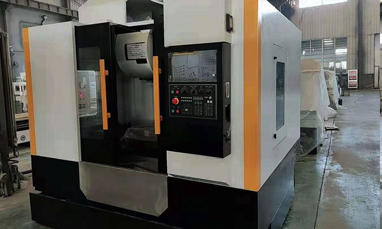
How to Assess a High Rigidity CNC Machine Tool
What Is a High Rigidity CNC Machine Tool
High Rigidity CNC Machine Tool is a CNC platform designed to resist deformation and vibration while cutting forces act on the spindle, toolholder, workpiece, fixture, machine structure, guideways, and drive system. For a manufacturing engineer, rigidity is not simply a catalog claim or a machine-weight comparison. It is the machine’s ability to hold the intended tool-to-workpiece position during real machining conditions. This directly affects dimensional consistency, surface finish, tool life, material removal strategy, and the risk of chatter. A machine may appear heavy yet still show weak behavior at specific spindle speeds, tool overhangs, axis positions, or fixture arrangements. Early technical qualification should therefore focus on measurable evidence. Ask suppliers how stiffness is measured, which structural position is tested, what cutting conditions were used, and whether test-cut records can be supplied before an RFQ is finalized.
Rigidity matters most when the process has limited tolerance for deflection. Examples include mold cavities with long tools, large-diameter boring, interrupted turning, deep-pocket milling, multi-face machining, and parts where a finish pass must remove only a controlled amount of material. The machine is only one part of the stiffness loop. Tool projection, holder type, fixture design, workpiece wall thickness, and cutting parameters also influence the result. A good qualification process separates machine capability from process limitations. This prevents a buyer from rejecting a suitable machine because of poor tooling, or accepting an unsuitable machine because a demonstration used easy material and shallow cuts.
Types of CNC Platforms That Need Different Rigidity Checks
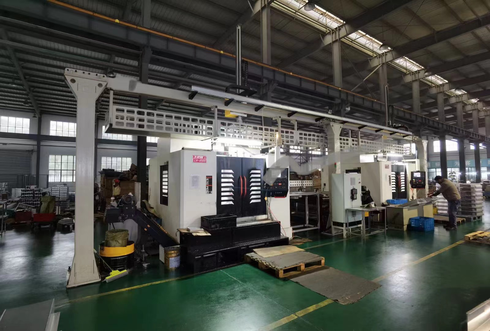
Different CNC architectures experience force in different directions, so buyers should assess the relevant load path instead of applying one generic checklist. A vertical machining center often requires close attention to spindle-head support, column behavior, table loading, and Z-axis response during deep cavity milling. A horizontal machine can be suitable where multi-face access, palletized work, or chip evacuation affects process stability, but the fixture and workholding arrangement still require review. On turning equipment, the bed, turret, spindle, chuck, tailstock, and part projection form the main rigidity chain. A cnc inclined bed lathe should therefore be evaluated with turning and boring conditions that reflect the planned part family, not with a generic light finishing demonstration.
- Vertical machining centers: Best assessed for column and spindle-head behavior, Z-axis loads, long-tool performance, and table-side fixture stability. They fit prismatic parts, plates, dies, and cavities, but results may change when tools extend far below the spindle face.
- Horizontal machining centers: Best assessed for multi-face machining, fixture access, side-cutting forces, and chip control. They fit parts requiring several orientations in one setup, but pallet or tombstone rigidity must be included in the evaluation.
- CNC lathes: Best assessed for radial cutting loads, interrupted cuts, boring-bar projection, workholding, and tailstock support. They fit shafts, flanges, rings, and rotational parts, but a thin unsupported workpiece can dominate the vibration result.
- Customized platforms: Best assessed against the actual part, fixture, automation interface, and process sequence. They fit unusual loading or handling requirements, but buyers should define acceptance conditions before design approval.
The practical recommendation is simple: qualify the architecture against the hardest common operation, not the easiest sample part. If a buyer expects most work to be aluminum finishing, a heavy-duty roughing demonstration has limited value. If the target work includes steel mold bases, deep milling, or intermittent cuts, light aluminum tests do not establish enough evidence. For machining-center selection, a professional cnc machining center solution should be reviewed in the context of actual tooling, clamping, and programmed toolpaths.
Compare Static Stiffness Dynamic Stiffness and Damping Measurements
Buyers should separate static stiffness, dynamic stiffness, and damping because each answers a different question. Machine weight alone cannot replace these measurements. Weight may contribute to a stable structure, but it does not show how the spindle head behaves at a given axis position, whether a connection has local compliance, or how quickly vibration decays after a disturbance. A supplier should identify the test direction, load point, machine position, setup condition, and measurement method. Without those details, stiffness figures from two suppliers cannot be treated as equivalent.
| Parameter | What It Measures | What It Affects in Machining | What Buyers Should Request | Limit of the Measurement |
|---|---|---|---|---|
| Static stiffness | Deflection under a controlled stationary force | Dimensional error under sustained cutting load, bore size variation, wall deflection, and position retention | Load direction, load point, axis location, fixture condition, and displacement record | Does not show vibration behavior at changing cutting frequencies |
| Dynamic stiffness | Resistance to displacement under changing or oscillating force | Chatter tendency, stability during interrupted cutting, heavy milling, and variable engagement | Frequency-response or modal test method, sensor location, and spindle or axis position | Results change with tooling, workholding, and machine configuration |
| Damping | How effectively vibration energy is dissipated after excitation | Vibration decay, surface quality, noise behavior, and the tendency for chatter to persist | Test method, response curve, and the conditions used for comparison | High damping cannot correct a fundamentally weak load path |
Static stiffness is the starting point. It shows how much the machine structure moves when a known force is applied. This is useful when the process creates steady directional loading, such as boring, face milling, or side milling with consistent engagement. A static test is especially relevant during early platform screening because it can reveal weak points in the bed-to-column connection, spindle-head support, turret arrangement, or workholding chain. However, a good static result does not prove the machine will resist chatter. Cutting forces are rarely constant, especially during interrupted cuts, changing tool engagement, cornering, or machining with long tools.
Dynamic stiffness explains behavior under changing cutting forces. A machine can show acceptable static deflection and still become unstable when the forcing frequency aligns with a structural mode. This is why a buyer should request evidence from representative cutting conditions or a frequency-response test. The conclusion to use is conditional: dynamic data is most relevant when the application includes interrupted cuts, variable wall thickness, long tools, heavy side milling, or demanding surface requirements. It is less decisive for light finishing with short tools and rigid workholding, where the process load may remain well below the machine’s unstable range.
Damping controls how vibration develops after disturbance. Better damping can reduce the duration and amplitude of vibration after a cutting interruption or force change. In practice, that can help protect surface finish and reduce chatter marks. Yet damping should not be used as a substitute for a stiff structure, correct guideway condition, suitable spindle support, or sound fixture design. A buyer should treat claims about vibration reduction carefully unless the supplier can state how the measurement was taken. Comparing an unloaded impact test to a heavy roughing test is not valid.
Features to Inspect Before Accepting a Rigidity Claim
Start with the structure and then trace the complete force path. MAKCNC states that many machine bodies use high-strength cast iron, including resin-sand castings, with aging treatment intended to support long-term accuracy and rigidity. The company also states that core transmission components such as ballscrews and guideways commonly use high-precision components from Taiwan or Germany. These are useful engineering signals, but they are not a replacement for machine-specific qualification data. The correct approach is to verify how the structural design, guideway arrangement, screw support, spindle assembly, and control behavior work together on the model being considered.
- Machine base and casting arrangement: Ask for drawings or photographs that show the bed, column, cross members, and major load paths. A broad, well-supported structure can improve force distribution. This check does not establish dynamic behavior by itself.
- Guideway and ballscrew support: Ask which axes carry the highest cutting loads and how guideways and screw supports are arranged. This matters for positional stability and reversal behavior. It does not replace a test of actual axis motion under load.
- Spindle-to-tool connection: Review spindle taper, toolholder choice, tool projection, and expected cutter diameter. Shorter projection generally improves the process loop, but it may not reach deep features.
- Control functions: For mold machining, MAKCNC describes intelligent feedforward and quadrant-transition compensation intended to address overcut marks, quadrant marks, and vibration-related surface patterns. These functions can support contour quality, but they cannot correct a loose fixture or unsuitable cutting conditions.
- Workholding interface: Confirm fixture mounting surfaces, clamping access, and the expected center of gravity. A rigid machine with a flexible fixture will still produce unstable cutting.
A common mistake is to compare only spindle power, machine mass, or guideway width. Those values may be relevant, yet none alone describes the total machining system. Another mistake is to accept a demonstration cut without confirming tool overhang, stock material, cutter type, radial engagement, axial depth, workholding, and programmed feed. The most useful evidence is evidence that resembles your planned process.
Use Test Cuts and Acceptance Data Before an RFQ
The best pre-RFQ method is a structured test plan that moves from documents to measured behavior. Ask the supplier to review your part drawing, material, tolerance requirements, workholding concept, and highest-risk features. Then define a test cut that creates the force direction and vibration risk expected in production. This can include a deep pocket, long-reach cavity, large bore, interrupted turning operation, or thin-wall feature. The test does not need to copy the whole part. It needs to reproduce the technical risk that determines whether the platform is suitable.
- Identify the limiting feature. Select the bore, wall, cavity, surface, or tolerance most likely to fail because of deflection or chatter. Do not choose a low-risk flat surface merely because it is easy to inspect.
- Define the full process loop. State material, stock condition, tool type, holder, tool projection, fixture, clamping force, coolant approach, and expected machining sequence.
- Set measurable acceptance items. Specify what will be checked after cutting, such as dimensional variation, surface marks, tool wear pattern, or stability during a particular toolpath. Avoid vague wording such as “good rigidity.”
- Record machine conditions. Capture spindle speed, feed, cutting engagement, axis position, program strategy, and any control settings that affect the result.
- Review repeatability. One favorable part may not show production stability. Where the risk justifies it, repeat the critical operation after thermal stabilization and with the same controlled setup.
- Separate machine and fixture findings. If vibration occurs, test whether it changes with shorter tooling, altered clamping, or different engagement. This helps determine whether the limitation is structural, process-related, or both.
For example, a mold manufacturer evaluating deep-cavity milling should not rely only on a short-tool face-milling sample. The relevant test uses the planned long-reach tool, similar material, an equivalent holder, and a fixture that represents the actual workpiece support. If chatter appears, reducing tool projection may solve the problem, but that solution does not apply if the cavity depth requires the original reach. The buyer then needs a different holder strategy, altered cutting parameters, a different machine configuration, or a revised process plan.
Price Factors and Procurement Limits
Rigidity-related cost is not limited to the machine purchase price. Structural mass, casting process, aging treatment, guideway system, spindle configuration, control options, inspection scope, fixture requirements, tooling, shipment, installation support, and acceptance testing can all affect the commercial package. Buyers should request a quotation that separates base machine supply from options needed for their verified process. This makes it easier to compare bids without assuming that two similarly sized machines include the same support level or test scope.
| Cost Area | Why It Changes the Budget | Buyer Action |
|---|---|---|
| Machine configuration | Spindle, axis arrangement, control functions, and structural options vary by application | List mandatory process requirements before asking for price |
| Tooling and holders | Tool projection and holder quality directly affect the rigidity loop | Include representative tooling in the technical review |
| Fixtures and workholding | Weak clamping can invalidate machine capability | Budget fixture design and verification separately |
| Acceptance testing | Special test cuts, inspection, and documentation may require added preparation | Define test requirements in the RFQ rather than after order placement |
| Service planning | Startup support and long-term maintenance affect operating risk | Confirm warranty scope, response process, and paid-service terms |
MAKCNC states that single-machine purchasing is available without a hard minimum order quantity, while multi-machine purchases may receive improved commercial terms relating to price, delivery, or after-sales service. Stated lead times are typically 1 to 6 months, so project schedules should account for the final configuration and acceptance scope rather than treating a standard lead time as a fixed promise. The standard stated warranty is 12 months after machine acceptance, with lifetime paid service available. Some tender projects may require a longer warranty arrangement, including three years of free warranty where specified. These terms should be written into the commercial and technical agreement for the specific order.
User Guide for Early Technical Qualification
Use the following checklist before releasing an RFQ. First, classify the main load: axial drilling, radial boring, side milling, interrupted turning, or long-reach cavity work. Second, identify the weakest likely element in the process loop: machine structure, spindle, holder, tool, fixture, or workpiece. Third, request static, dynamic, and damping evidence with test conditions attached. Fourth, compare evidence only when the test direction and setup are similar. Fifth, plan a representative test cut for the highest-risk operation. Finally, write the acceptance criteria in measurable language so that both purchasing and engineering teams interpret the requirement the same way.
Do not apply the same standard to every job. A short, rigid milling cutter on a fully supported workpiece may not require an advanced dynamic study. A long boring bar machining a deep internal feature may require much closer review. Likewise, a machine selected for occasional prototype work can be acceptable with a broader operating window than a platform intended for repeated production of tolerance-sensitive components. The required evidence should match the cost of failure, the planned duty cycle, and the part quality risk.
MAKCNC as a CNC Machine Supplier
MAKCNC was established in 2016 and operates multiple production lines with sample-machine inventory stated in its company information. For buyers assessing a new CNC platform, this can support earlier discussions around machine configuration and representative evaluation. The company supplies CNC lathing machines, CNC machining centers, and CNC machines for applications that may require rigid structural design, precision transmission components, and process-specific control support. Buyers can also review about makcnc when preparing a supplier qualification file. The appropriate supplier discussion should cover your drawings, materials, tolerance targets, tooling reach, fixture plan, and acceptance test conditions rather than relying on a general claim about machine rigidity.
FAQ of Machine Rigidity Assessment
Is a heavier machine always more rigid?
No. Machine weight can indicate a substantial structure, but it does not measure stiffness at the spindle nose, table, turret, or tool tip. It also does not show dynamic response or damping. Use weight as a preliminary reference only, then request structural information and test evidence.
What data should a supplier provide for a rigidity review?
Request test direction, loading point, axis position, tooling condition, fixture condition, measurement method, and recorded result. For a cutting demonstration, request material, cutter, holder, tool projection, spindle speed, feed, engagement, and inspection results. Data without conditions cannot be compared reliably.
Can control compensation replace mechanical rigidity?
No. Control functions can help manage contour behavior and transition-related marks, but they do not remove structural deflection, excessive tool overhang, or fixture vibration. Use compensation as part of the overall machine-and-process system.
When should a buyer request a representative test cut?
Request one when the intended work includes difficult materials, long tools, deep bores, thin walls, interrupted cuts, strict surface expectations, or tolerance-sensitive features. For simple low-load operations, document review may be sufficient during early screening.
If you are sourcing a CNC platform for demanding machining, contact MAKCNC with your drawings and process requirements to request selection advice and a current quotation.