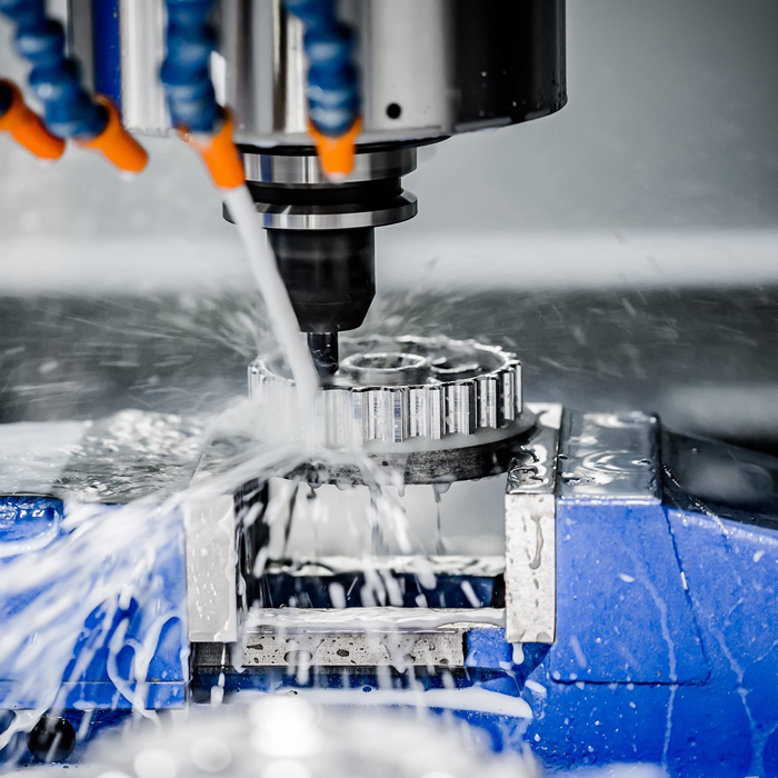
Match Industrial CNC Lathing Equipment to Part Mix
What Is Industrial CNC Lathing Equipment?
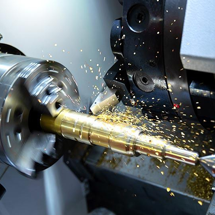
Industrial CNC Lathing Equipment is a machine category that rotates a workpiece while programmed tools perform turning operations such as facing, outside-diameter turning, boring, threading, grooving, and parting. The main buying decision is not simply whether a machine can make a part. It is whether the spindle arrangement, turret capacity, workholding method, and material-handling approach suit the part families and batch pattern your plant actually runs. Computer numerical control allows repeatable programmed tool movements, but the production result still depends on selecting a machine layout that fits the workpiece. A long shaft, a short flange, and a bar-fed connector may all be turned parts, yet they place very different demands on support, clamping, cycle planning, and unloading. For early equipment evaluation, classify the existing and expected part mix before comparing machine specifications.
Types of CNC Lathing Machine Configurations
The useful way to group lathing machines is by how the part enters the spindle, how it is held during machining, and how frequently the machine must change between part references. A chucking configuration is normally evaluated for shorter blanks, forgings, castings, or pre-cut material that can be gripped directly. A bar-work configuration is evaluated when compatible material is supplied in bar form and multiple parts can be produced from one loading cycle. An inclined-bed format may be considered where chip flow, operator access, and turret-based machining are priorities; see the available cnc inclined bed lathe range when reviewing this machine layout. The correct type is determined by the dominant workload, not by the most unusual drawing in the quotation package. If a low-volume outlier needs a special fixture or an extra operation, it may be better handled separately than forcing the main production machine into an unsuitable configuration.
Choose the base layout from the dominant production constraint
- Choose a chuck-oriented setup when parts arrive as cut blanks, forgings, castings, or irregular preforms. The reason is direct gripping is the starting point for these workpieces. It fits flange bodies and short housings. It may not be the best first choice for unattended runs from continuous bar material.
- Choose a bar-oriented setup when the majority of parts are rotational, repeat frequently, and begin from bar material. This approach fits connectors, sleeves, pins, and similar repeat parts. It is less suitable when the starting stock is too irregular for bar feeding or when part geometry depends on features better produced from a chuck-held blank.
- Choose a shaft-focused arrangement when work length and support needs govern the process. The reason is that a long rotating workpiece requires a stable holding and support plan, rather than just sufficient turning capability. It may not be justified for a plant dominated by compact parts.
- Choose a turning center with a capable turret plan when one setup must include several tool operations. This fits recurring turned parts with faces, diameters, grooves, bores, and threads. It does not remove the need to verify tool positions, interference, and the full machining sequence against the drawing.
Application Mapping for Shaft Flange Bar Stock and Chucking Parts
Part family mapping should be the first working document used by production managers, process engineers, and OEM buyers. It turns a broad equipment conversation into a practical configuration request. The table below is a general application analysis, not a record of a completed customer project. It identifies which configuration direction usually deserves evaluation and where the buyer must stop and confirm the details through drawings, sample material, and cycle planning.
| Part family | Typical production condition | Spindle and workholding direction | Turret direction | Automation direction | Boundary to check before selection |
|---|---|---|---|---|---|
| Shafts | Long rotational parts with several turned diameters, shoulders, threads, or grooves | Evaluate workholding and support suitable for the finished length and clamping locations | Plan tools in operation order so turning, grooving, threading, and finishing can be completed without unnecessary reclamping | Automation is evaluated only after loading orientation and finished-part handling are defined | Do not assume a standard chucking setup is sufficient when length, deflection risk, or support access controls the process |
| Flanges | Short, wider parts with face features, bores, and outside diameters | Evaluate direct chucking or dedicated workholding based on gripping surfaces and datum requirements | Use a turret plan that supports facing, boring, turning, and groove or thread operations where required | Suitable for repeatable loading when part orientation and safe gripping are consistent | Do not select only by maximum swing; fixture access and clamping distortion must be reviewed |
| Bar-stock parts | Repeat families of pins, bushes, connectors, sleeves, or threaded components from compatible bar material | Evaluate bar-capable spindle loading and collet or appropriate gripping arrangements | Prioritize the recurring sequence of outside turning, drilling, boring, threading, grooving, and cutoff | Bar handling can be considered when material form, part length, cutoff handling, and batch demand support it | Not suitable as an assumed solution for forged, cast, irregular, or pre-cut blanks |
| Chucking parts | Pre-cut blanks, castings, forgings, or parts with shapes not suited to bar feed | Evaluate chuck jaws, fixture concepts, and repeatable datum control | Arrange tools around the operations achievable from the selected clamping position | Consider loading assistance only after the part can be safely and repeatably presented to the chuck | Do not treat automation as a substitute for stable workholding or safe loading orientation |
The clear recommendation is to request configuration review by part family, rather than submitting a mixed drawing pack with no production context. For example, a buyer with recurring bar-stock connectors and occasional flange work should identify which family consumes most spindle time and which family drives delivery requirements. If connectors account for the main production load, bar handling and a turret sequence may deserve priority. If the flange work is more commercially important, direct chucking and fixture access may be the governing factors. Neither route is automatically superior. The correct direction depends on forecast volume, starting material, tolerance requirements stated on the drawing, secondary operations, and the expected changeover frequency.
Features That Matter Before You Compare Machine Specifications
Buyers should assess equipment features as a connected system. A spindle, turret, guideway arrangement, control system, fixture, and loading method each affect the others. MAKCNC states that many machine bodies use high-strength cast iron, including resin-sand castings, with aging treatment intended to support long-term rigidity and accuracy. Core transmission components such as ball screws and guideways may use high-precision components from Taiwan or Germany. These are relevant manufacturing details, but they do not replace application validation. A buyer should still confirm whether the proposed machine can hold the workpiece, present each tool, manage chips, and complete the intended operations from the chosen datum.
- Spindle and workholding first: Confirm the raw material form, gripping diameter range needed, clamping surfaces, and whether a second setup is planned. This fits every part family because holding controls datum stability. It does not answer the tooling question by itself.
- Turret layout second: List every turning, boring, drilling, grooving, threading, and cutoff operation in sequence. This fits parts with multiple turning features. It is not enough for parts that need milling, cross holes, or non-turned geometry beyond the selected machine’s intended process scope.
- Control strategy third: For mold-industry accuracy requirements, MAKCNC describes system integration with intelligent feedforward and quadrant-transition compensation intended to address issues such as overcut marks, quadrant marks, and chatter-related patterns. Buyers should treat this as a capability area to discuss for the proposed application, not as a replacement for correct tooling, clamping, programming, and cutting conditions.
- Automation last: Specify loading, unloading, part orientation, inspection handoff, and operator intervention points. This fits repeatable part families. It does not fit an undefined process where workholding and raw-material presentation are still unresolved.
Industrial CNC Lathing Equipment Price Factors and RFQ Inputs
Price variation is driven by the configuration needed to produce the intended part mix, not by a single label such as “CNC lathe.” An RFQ should separate the base machine request from process-specific requirements. The useful commercial conclusion is simple: ask suppliers to price a defined operating concept, then compare what is included and what still requires engineering confirmation. MAKCNC states that there is no hard minimum order quantity, so a single machine can be purchased, while multi-machine orders may receive improved commercial terms on price, delivery, or after-sales service. The stated lead time is typically one to six months. These points can support phased purchasing, but they are not a reason to postpone defining the application.
| Price driver | What to provide in the RFQ | Why it affects the proposal |
|---|---|---|
| Part mix | Part drawings, annual or monthly demand pattern, and the share of shaft, flange, bar-stock, and chucking work | Determines the configuration direction and changeover expectations |
| Raw material condition | Bar, cut blank, forging, casting, or customer-supplied preform | Determines loading, gripping, and possible automation approach |
| Operation sequence | List of required turning operations and any features requiring other processes | Defines turret planning and whether a separate machining operation is needed |
| Workholding requirement | Required datum, clamping area, jaw or fixture concept, and any part deformation concern | Prevents a proposal based on an unsuitable gripping assumption |
| Support expectation | Site location, acceptance expectation, training need, and service requirement | Sets the commercial support scope before purchase approval |
Do not compare quotations only by the machine headline. Compare the stated machine scope, included workholding, tooling assumptions, automation interface, documentation, acceptance method, delivery basis, and service terms. MAKCNC’s usual warranty is 12 months after full-machine acceptance, with lifetime paid service available. Some tender projects may require a longer free warranty period, including three years. The after-sales network commonly commits to an eight-hour response and on-site fault handling within 48 hours. Buyers should confirm the applicable terms in the final quotation and contract, especially for overseas installation conditions and tender-specific requirements.
User Guide for Evaluating the Right Production Setup
A disciplined selection procedure reduces the risk of buying a machine that is technically capable but operationally mismatched. Start with representative parts, not only the simplest drawing. Include the parts that create the highest setup burden, the longest cycle path, the most demanding clamping condition, and the highest expected order frequency. Then build an evaluation package that every supplier can review on the same basis. If a part needs turning plus substantial prismatic machining, assess whether process splitting is sensible. A professional cnc machining center solution may be relevant for non-turned operations, but it should be evaluated as part of the full routing rather than added without a defined handoff between machines.
- Sort the drawings into four groups: shafts, flanges, bar-stock parts, and chucking parts. Mark low-volume exceptions separately.
- Identify the routing: record which operations are completed in turning and which require another process, inspection point, or manual intervention.
- Define the initial datum and final datum: confirm where the part is held first and what surfaces must remain accessible.
- State the batch pattern: distinguish recurring production from occasional replacement work. This determines whether changeover flexibility or material handling deserves more attention.
- Request a configuration response: ask the supplier to explain the proposed spindle, turret, workholding, and automation assumptions against the part families.
- Review exclusions: list every feature, operation, material condition, or tolerance requirement that has not been confirmed by the supplier.
- Agree on acceptance criteria: establish the drawings, inspection approach, and documentation required before placing the order.
Common Selection Mistakes That Create Production Gaps
The most expensive errors usually occur before the purchase order. They are often planning errors rather than machine defects. Avoid selecting equipment from a product image, a broad maximum-capacity statement, or an assumed automation concept. A machine can be appropriate for one part group and still be a poor fit for the mix that generates most of the plant’s revenue. Use the following checks during technical and commercial review.
- Choosing from the largest drawing only: This can lead to an oversized configuration that is inefficient for the recurring smaller work. Review the frequency and value of each part family instead.
- Treating bar feed as universal: Bar-oriented production needs compatible material presentation and a suitable part design. Use chucking or fixture-based loading where raw stock or geometry makes bar feeding unsuitable.
- Ignoring the second operation: A turning solution should not be judged as a complete route if the drawing also needs machining outside the turning process. Define the transfer, datum, and inspection plan.
- Leaving workholding until after ordering: Clamping access, datum position, and deformation concerns can change the process direction. Review them before selecting the machine.
- Assuming service terms without contract review: Warranty and response arrangements must be confirmed for the actual project scope and destination.
MAKCNC Supplier Support for Part Mix Evaluation
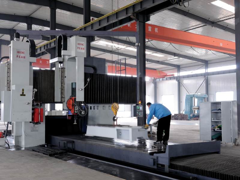
MAKCNC was established in 2016 and operates multiple production lines with sample machine inventory. The company lists S09001:2015 and supplies CNC lathing machines, CNC machining centers, and CNC machines for buyers developing a suitable process route. For a buyer evaluating a defined turned-part portfolio, the useful starting point is a drawing package paired with production information: part family, starting material, expected batch pattern, required operations, workholding concerns, and site service expectations. Where standard layouts do not fit the required process, review customized cnc machines and machining centers from makcnc only after the process boundaries are clear. A custom request is most effective when it solves a documented handling, clamping, or routing issue rather than an undefined preference.
If you are sourcing a CNC lathing equipment supplier, send MAKCNC your representative drawings and part-mix details to request selection advice and a current quotation.