
How to Maintain Precision with a Vertical Machining Center for Mold Making in Deep Cavities
A professional cnc machining center solution is essential for mold production, but even the best equipment can produce defects when machining deep cavities. When you discover tapered walls, dimensional drift, or poor surface finishes deep inside a core or cavity, it's a clear sign that cutting forces, thermal effects, or setup issues are compromising the machine's performance. Understanding the root cause is the first step toward a solution. For a vertical machining center for mold making, the challenge is amplified by gravity's effect on chip evacuation and the long tool overhangs required to reach the bottom of a feature. These factors introduce variables that can lead to costly rework or scrapped molds if not properly managed.
This guide provides a diagnostic framework to identify why your machine is losing accuracy in deep pockets. We will analyze the boundaries where common issues arise and outline the machine characteristics and control technologies required to overcome them, ensuring your finished molds meet strict dimensional and surface quality standards.
Diagnosing Inaccuracy: A Boundary Analysis for Deep Mold Machining
When a deep cavity machining operation fails, the defect itself provides clues to the underlying problem. Instead of guessing, a structured diagnostic approach can quickly isolate the cause. The three most common culprits are excessive tool overhang, poor chip evacuation, and uncontrolled thermal growth. Use the following troubleshooting order to determine where your process is breaking down.
This analysis helps you decide if the problem requires a process adjustment (e.g., different tool, changed CAM path) or if it indicates a fundamental limitation of the machine's capability for that specific job.
| Symptom / Defect | Primary Suspect & What to Check First | Diagnostic Criteria | Secondary Causes to Investigate |
|---|---|---|---|
| Cavity Taper (Walls are not parallel; bottom is wider/narrower than the top) | Tool Overhang & Deflection Check the tool's length-to-diameter (L/D) ratio. |
If L/D ratio exceeds 4:1, deflection is the likely cause. The tool is bending under cutting forces. Measure the taper; if it's consistent on all walls, this points strongly to tool deflection. | Machine Rigidity: A less rigid machine frame or spindle will amplify deflection. Spindle bearing wear can also contribute. |
| Poor Surface Finish / Chatter Marks (Visible vibration patterns on walls or floor) | Tool Overhang & Rigidity Listen for high-pitched sounds during cutting and inspect the tool holder interface (e.g., BT40, HSK). |
Chatter occurs when the cutting assembly's natural frequency is excited. This is common with long, slender tools. If marks appear at specific depths or during cornering, it's a vibration issue. Ensure the tool holder and spindle taper are clean and properly clamped. | Chip Recutting: Trapped chips can induce vibration and mar the surface. Check if chip evacuation is effective. |
| Dimensional Drift (Features are out of position, especially after long cycles) | Thermal Growth Check the temperature of the spindle, ballscrews, and machine structure after a long run. |
If parts made at the beginning of the day are accurate but those made hours later are not, thermal expansion is the primary suspect. Heat from the spindle and axis motors causes machine components to grow, shifting the tool's position. | Foundation Instability: Environmental temperature swings or an unstable machine foundation can also cause gradual positional changes. |
| Inconsistent Floor Finish / Tool Marks on Cavity Bottom | Chip Evacuation Inspect the cavity during and after machining. Are chips packing in the corners? |
If chips are not effectively removed by coolant or air blast, the tool will recut them. This dulls the tool, increases cutting forces, and scores the workpiece surface, creating a poor finish. It is a major issue in deep, narrow pockets. | Coolant Pressure/Volume: The coolant system may be inadequate for the depth, failing to flush chips up and out of the cutting zone. |
Core Machine Characteristics for Mold Making Accuracy
A machine's ability to resist the forces detailed above is not accidental; it is determined by its fundamental design and construction. For shops focused on high-tolerance mold making, certain features are non-negotiable. These elements provide the stable platform needed to execute precise, demanding cuts deep inside a workpiece.
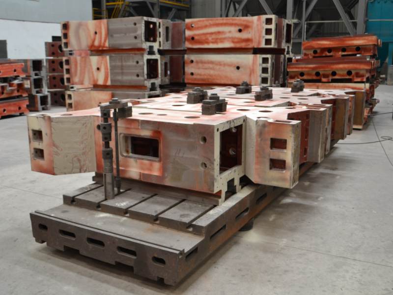
Our machine bodies are constructed from high-strength cast iron, such as resin sand castings, which provides superior vibration damping compared to welded steel frames. After casting, these core components undergo an aging treatment process. This critical step relieves internal stresses within the material, ensuring the machine's geometric accuracy and rigidity are maintained over years of heavy use and thermal cycles. This long-term stability is foundational to producing accurate molds consistently.
Key Structural and Component Checklist
- Base and Column Construction: Is the machine built on a heavy, stress-relieved cast iron frame? A solid foundation resists deflection and absorbs cutting vibrations, which is especially important when using long tools that can induce chatter.
- Core Drive Components: The precision of a machine is directly tied to its motion system. We utilize high-precision components, often from established Taiwanese or German brands, for critical parts like ballscrews and linear guideways. This ensures smooth, accurate, and repeatable positioning without backlash.
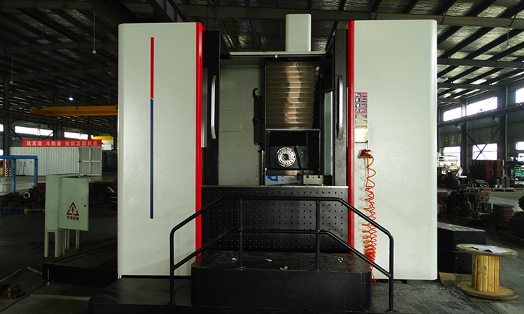
- System Synergy and Integration: High-quality components alone are not enough. The entire system must be engineered to work in concert. Our design process focuses on this system-level integration to achieve the machine's optimal performance, turning quality parts into a genuinely accurate vertical cnc machining center mv1380.
- Spindle Quality: The spindle must have minimal runout and be thermally stable to prevent tool position drift during long machining cycles. A robust spindle design with high-quality bearings is essential for holding tight tolerances.
Advanced Control Systems That Eliminate Common Mold Flaws
Beyond mechanical rigidity, modern CNC controls offer intelligent features specifically designed to address the challenges of high-precision 3D contouring required in mold making. These software and control functions anticipate and correct for errors that would otherwise manifest as visible flaws on the finished part.
For the specific demands of the mold and die industry, our machines integrate advanced system technologies to solve common machining headaches. These include:
- Intelligent Look-Ahead and Feedforward: The control analyzes the toolpath code many blocks ahead, allowing it to accelerate and decelerate smoothly without pausing. This prevents the "dwell marks" that can occur as the machine navigates complex geometry. Intelligent feedforward actively compensates for the tiny dynamic errors that occur during axis reversals.
- Over-Quadrant Glitch Compensation: When a tool path involves circular movements or changes direction at a quadrant (0°, 90°, 180°, 270°), mechanical backlash or servo mismatch can cause a small "bump" or gouge. Our systems include compensation technologies to smooth this transition, effectively eliminating these "quadrant glitches" or "witness marks."
- Vibration and Chatter Suppression: Advanced algorithms can monitor for the onset of chatter and automatically adjust spindle speed or feed rates to move out of the unstable frequency range. This helps prevent "chatter marks" or "knife-edge patterns" on the workpiece surface, preserving the required finish.
For shops producing a variety of parts, these machines also provide the flexibility for multi-sided machining in a single clamping. This capability reduces setup time and improves accuracy by eliminating the potential for tolerance stacking that occurs when a part is moved and re-fixtured.
Your Partner for High-Precision CNC Solutions
Since our founding in 2016, MAKCNC has been dedicated to providing reliable and precise CNC machinery. Our operations are managed within an ISO9001:2015 certified facility, ensuring consistent quality in every machine we build. We operate multiple production lines and maintain an inventory of sample machines, allowing us to offer flexible delivery timelines, typically ranging from one to six months depending on the model and customization.
We understand that every business has different purchasing needs. That's why we have no rigid minimum order quantity; you can procure a single machine. However, for clients placing bulk orders, we are pleased to offer more favorable commercial terms regarding price, delivery schedule, or after-sales support. More information about our company and mission is available on our about makcnc, professional cnc lathing machine manufacturer page.
Our commitment extends beyond the sale. A standard machine warranty covers 12 months after acceptance, with lifetime paid service available. For specific tender projects with higher requirements, we can accommodate extended warranties, such as three years of free coverage. Our mature after-sales network is built for responsiveness, with a commitment to reply within 8 hours and have a technician on-site to address any faults within 48 hours.
If your mold-making operations demand higher accuracy and a reliable machining partner, let's discuss your requirements. Contact us to submit your drawings and receive a detailed quote for a machine configured to your needs.