
Machining Center CNC 9 Common Alarm Codes Explained
What Is Machining Center CNC
machining center cnc describes a computer-controlled machine tool that can mill, drill, tap, bore, and perform related cutting operations in one setup. A typical machine combines a spindle, worktable, automatic tool changer, servo-driven axes, coolant system, and numerical control unit. When the controller detects an abnormal condition, it may stop the machine or restrict movement and display an alarm message. This protection helps prevent injury and limits damage to the workpiece, spindle, tooling, and machine structure. However, an alarm code alone does not always pinpoint the failed component. Operators need to consider the code, message text, machine position, recent operation, and any electrical or mechanical symptoms together. This guide covers nine common alarm conditions and practical first checks for maintenance teams, buyers, and production managers.
Types of Machining Center CNC
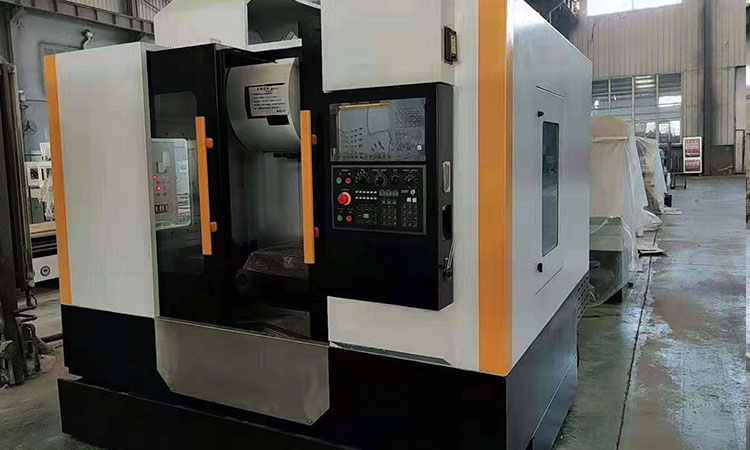
Machining centers are generally available in vertical, horizontal, gantry, and application-specific configurations. A vertical model positions the spindle above the workpiece and is widely used for molds, plates, brackets, housings, and general precision components. Horizontal machines offer effective chip evacuation and are often selected for larger parts or multi-face production. Gantry equipment provides a large work envelope for dies, structural parts, and heavy workpieces. Buyers may also compare three-axis, four-axis, and five-axis layouts, as well as spindle speed, table size, tool capacity, and control brand. MAKCNC supplies vertical and horizontal options, including the vertical cnc machining center mv1380 for larger workpieces and demanding production requirements.
Features of Machining Center CNC
The value of a modern machining center comes from controlled motion, repeatable positioning, and the ability to complete multiple operations without transferring the workpiece between machines. High-speed spindles are well suited to aluminum and nonferrous alloys, while high-torque spindle packages are typically a better match for steel, cast iron, and demanding cuts. Linear guides, precision ball screws, automatic lubrication, rigid columns, and a stable machine base all influence machining performance. A dependable control system also records machine status, tool offsets, spindle load, and alarm history. During CNC machine troubleshooting, these details offer useful clues. For instance, an overload alarm paired with steadily rising spindle load may point to a dull tool, excessive depth of cut, poor workholding, or a developing mechanical issue.
Machining Center CNC Application
These machines are used in communication equipment, consumer electronics, automotive components, aerospace parts, mineral machinery, agricultural equipment, chemical equipment, petroleum tools, water conservancy projects, and geological exploration products. A vertical unit may machine a 6061 aluminum communication housing with drilling, pocketing, and tapping in one setup. A horizontal machine can process several faces of a cast-iron gearbox housing while reducing repeated fixture changes. Oilfield suppliers often require large, accurate components and may pair machining centers with CNC lathes. Production teams should select equipment based on material, workpiece dimensions, tolerances, batch size, and available service support. The right machine choice helps prevent avoidable alarms because the spindle, axis travel, table load, and tool system match the actual production task.
Machining Center CNC Price
Machining center prices vary according to machine size, spindle power, travel range, control system, tool magazine capacity, automation level, accuracy requirements, and shipping destination. A compact three-axis machine for aluminum prototypes will not cost the same as a large horizontal center with a pallet changer, fourth-axis equipment, probing, and chip management. Buyers should also include installation, operator training, electrical preparation, foundation work, spare parts, tooling, and local service in their budget. The lowest initial quotation is not necessarily the lowest long-term operating cost, especially if the machine needs frequent adjustment or has limited support. Request a technical quotation based on drawings, materials, target cycle time, annual volume, and preferred options rather than relying on a general catalog price.
Machining Center CNC User Guide
Before production begins, verify machine level, power supply, grounding, compressed-air quality, coolant concentration, lubrication level, and hydraulic pressure where applicable. Confirm that the workholding device is secure and that tool offsets match the tools loaded in the magazine. Run a dry cycle above the workpiece, particularly after changing a program, fixture, or tool setup. Operators should read the alarm number and save the screen before repeatedly pressing reset. Record the active program block, axis coordinates, spindle speed, feed rate, tool number, and recent maintenance activity. Resetting the control may clear the display, but it does not remove the underlying cause. Never reach into the enclosure until the spindle has stopped, stored energy has been isolated, and the machine is safe under site procedures.
9 Common Machining Center CNC Alarm Codes
1. Servo Alarm and Drive Fault Codes
Servo alarms are among the most common CNC machining center alarms. Depending on the control brand, a servo or drive fault may appear as a 100-series alarm, an amplifier alarm, or a message such as “servo error” or “drive not ready.” Common causes include an overloaded axis, collision, blocked slide, damaged feedback cable, loose motor connection, amplifier fault, or unstable incoming power. First note which axis is identified and whether the alarm occurred during rapid travel, cutting, homing, or tool changing. Inspect the machine for visible obstructions, excess chips, and damaged cables. If the alarm returns immediately after reset, do not continue cycling the machine. A qualified technician should test motor insulation, encoder feedback, drive status, and axis mechanics.
2. Axis Overtravel Alarm
An overtravel condition occurs when an axis reaches a software limit or activates a physical limit switch. Some controls show a negative or positive overtravel code, while others display the affected axis and direction in plain text. Likely causes include an incorrect work coordinate, an incorrect machine-coordinate reference, a bad program value, failed home positioning, or a limit switch triggered by unexpected movement. Check the displayed axis position and compare it with the programmed travel. Use the control’s approved manual recovery function to move away from the limit; never force the axis or bypass a safety switch. If an axis reports overtravel in the middle of its normal range, inspect limit switches, wiring, ballscrew condition, and reference-return accuracy. This is an important part of machining center error codes analysis.
3. Spindle Orientation or Spindle Drive Alarm
Spindle alarms can interrupt cutting, tool changes, rigid tapping, or orientation. A controller may display a spindle drive fault, orientation error, overload message, or a code in the 500-series, although exact code numbers vary by manufacturer. Possible causes include excessive cutting load, an incorrect speed command, spindle motor damage, encoder feedback failure, low drive voltage, poor lubrication, or a tool that is not seated correctly. Check whether the spindle turns freely at low speed, whether the alarm appears at startup or only under load, and whether spindle load increased before the stop. What causes CNC machining center spindle alarms is often a combination of tooling condition and machine condition rather than a single electronic failure. Stop production immediately if there is abnormal noise, heat, smoke, or vibration.
4. Tool Changer Position or Tool Clamp Alarm
An automatic tool changer alarm may indicate that the arm is not in position, the magazine is not ready, the tool is unclamped, or spindle orientation is incomplete. Generic examples include 200-series or 300-series tool-change messages, but the exact number depends on the control and machine builder. Chips around the taper, a damaged pull stud, low air pressure, a misaligned magazine pocket, sensor contamination, or a failed solenoid can interrupt the tool-change sequence. Review the tool number requested by the program and compare it with the magazine position. Confirm air pressure and inspect the taper without placing hands near moving parts. Manual recovery must follow the machine manual step by step. If the arm is mechanically jammed, professional service is safer than repeated reset commands.
5. Coolant Level or Coolant Pump Alarm
Coolant-related alarms may identify a low tank level, pump overload, blocked filter, flow failure, or high-temperature condition. On some machines, a coolant alarm stops the spindle; on others, it serves as a warning only. Check the tank level, coolant concentration, pump inlet, return line, filter, and nozzle position. A clogged filter can reduce flow even when the tank is full. Excessive foam may signal an incorrect mixture or contamination from tramp oil. A pump that hums but does not move fluid may have a blocked impeller or an electrical fault. Keep coolant away from open electrical cabinets and clean spills promptly. If the alarm returns after checking the tank and filter, an electrician or service engineer should test the pump motor, overload relay, flow sensor, and control output.
6. Lubrication Pressure or Low Oil Alarm
Automatic lubrication protects guideways, ball screws, and other sliding or rotating components. A low-oil or lubrication-pressure alarm may appear when the reservoir is empty, a metering line is blocked, the pump fails, or a pressure switch does not respond. The machine may continue for a short time, but ignoring the message can lead to expensive guideway and ballscrew wear. Check the approved lubricant type, reservoir level, pump cycle, and visible distribution lines. Never substitute hydraulic oil or general-purpose oil without confirmation from the machine builder. If oil is present but pressure does not build, inspect the pump, filter, distribution manifold, and pressure sensor. A service technician should verify actual oil delivery, as a full reservoir does not prove that lubricant is reaching every lubrication point.
7. Memory, Program, or Communication Alarm
Control-system alarms may involve program memory, data transfer, parameter protection, battery condition, or communication between the CNC and connected equipment. Messages such as memory parity error, input/output communication error, or program format error can appear after a file transfer, parameter change, power interruption, or an aging control battery. Save the alarm screen and avoid changing parameters without a verified backup. Check the program format, file name, transfer cable, network connection, and available memory. If the control battery is weak, data loss can occur when power is removed. This is where CNC diagnostics should be methodical: compare alarm history, backup files, I/O status, and control voltage. Parameter restoration should be handled by trained personnel because an incorrect value can affect axis motion or machine safety.
8. Door, Safety Interlock, or Emergency Stop Alarm
A safety alarm means the control has detected an open door, activated emergency stop, failed interlock, light-curtain interruption, or safety-circuit problem. It may result from a genuinely open enclosure, a misadjusted door switch, damaged wiring, a failed relay, or an emergency-stop button that has not fully released. Check the physical condition of every safety device and make sure doors close completely. Do not bypass an interlock simply to keep production running. If the message remains after the obvious condition has been corrected, a qualified electrician should trace the safety circuit using the machine’s electrical drawings. Safety circuits are designed to prevent spindle and axis movement in hazardous conditions. Treating this alarm as a nuisance can expose operators to serious injury.
9. Excessive Following Error or Position Deviation
A following-error alarm means the commanded axis position and actual position have separated beyond the control’s permitted value. It can result from a collision, an aggressive feed rate, a stuck slide, worn mechanical transmission, loose coupling, encoder issue, or servo tuning problem. Some controls identify this with a following-error, position-error, or axis-deviation code. Note whether it affects one axis or several, and whether it appears during rapid movement or heavy cutting. Inspect the work envelope for obstructions and check for unusual mechanical resistance, but do not manually force the axis. A recurring deviation requires measurement of backlash, coupling condition, servo gain, encoder feedback, and ballscrew movement. Continued operation can damage the axis drive and reduce part accuracy.
How to Troubleshoot Machining Center CNC Alarm Codes
To learn how to troubleshoot machining center CNC alarm codes, follow a consistent sequence rather than clearing alarms at random. First, make the machine safe and record the complete message, code, axis, tool number, program block, and time. Next, determine whether the issue is mechanical, electrical, hydraulic, pneumatic, coolant-related, or program-related. Check simple external conditions such as incoming power, air pressure, oil, coolant, door position, and tool seating. Then review alarm history and I/O screens if the operator has been trained to use them. Compare the current event with the maintenance log. If the alarm follows a collision, smoke, burning smell, repeated drive trip, uncontrolled axis movement, or damaged cable, stop and request professional support. Clear records help MAKCNC or a local engineer reduce diagnosis time.
How to Diagnose CNC Machine Axis Errors
When considering how to diagnose CNC machine axis errors, start with the affected axis and the exact operating condition. An error during reference return may point to the home switch, encoder, reference signal, or a travel obstruction. An error during cutting can indicate excessive load, tool interference, poor workholding, backlash, or servo tuning issues. Listen for unusual sounds, check whether the axis moves smoothly at low speed, and inspect lubrication and visible chip buildup. Compare commanded and actual positions without changing servo parameters. A laser interferometer, dial indicator, ballbar test, insulation meter, or oscilloscope may be needed for a final diagnosis. These tests should be completed by trained service personnel, especially when the machine remains under warranty or the control cabinet must be opened.
Machining Center CNC Supplier
MAKCNC supplies CNC lathing machines, CNC machining centers, and CNC machines for industrial buyers seeking dependable production equipment. Our product range includes vertical machining center series, horizontal machining center series, gantry processing series, heavy-duty cutting lathes, CNC oilfield lathes, and CNC lathe series. Recommended machining center models include the vertical cnc machining center mv1270, vertical cnc machining center mv1160, and the horizontal cnc machining center. We can also discuss customized cnc machines and machining centers from makcnc when standard travel, tooling, automation, or workholding does not suit your process. For machine specifications, application advice, and the latest quotation, contact the about makcnc professional cnc lathing machine manufacturer team.
FAQ of Machining Center CNC
How to troubleshoot machining center CNC alarm codes safely?
Start by stopping the machine and protecting the operator, workpiece, and tooling. Record the alarm number, wording, axis, tool, program line, and machine condition before pressing reset. Check basic items such as emergency-stop release, door closure, air pressure, coolant level, lubrication, tool seating, and visible obstructions. Read the machine manual because the same number can mean different things on different control brands. If the alarm returns immediately, follows a collision, or involves servo, spindle, safety, or electrical hardware, stop testing and contact qualified service personnel. Repeated resets can hide the original event and may cause additional damage.
What causes CNC machining center spindle alarms?
Spindle alarms may result from excessive cutting load, a dull or incorrectly selected tool, incorrect speed programming, poor tool seating, insufficient lubrication, overheating, encoder failure, drive faults, unstable power, or a mechanical issue within the spindle assembly. Check when the alarm occurs. An alarm at startup points more toward drive, feedback, orientation, or lubrication conditions, while an alarm that appears only during cutting may relate to load, tooling, material, or chip evacuation. Inspect for vibration, noise, heat, and abnormal spindle-load readings. Do not continue operating if smoke, grinding noise, or severe vibration appears. A service engineer may need to test the spindle motor, encoder, drive, bearings, and lubrication system.
When should a buyer request professional CNC diagnostics?
Professional CNC diagnostics are appropriate when an alarm repeats after basic checks, when the machine has experienced a collision, or when the fault involves a servo drive, spindle, encoder, safety circuit, parameter, or electrical cabinet. Service support is also recommended when parts suddenly lose accuracy, axis movement becomes uneven, or alarms appear across several systems at once. Buyers should keep alarm history, maintenance records, photos, control screenshots, and a description of the operation that triggered the fault. This information helps the supplier identify likely spare parts and prepare a more useful service response. MAKCNC can discuss machine selection, operating requirements, and support needs before purchase.
Choose MAKCNC for Your CNC Machine
Correct alarm handling protects uptime, part quality, and employee safety, while proper machine selection can reduce avoidable faults from the start. MAKCNC designs and supplies equipment with attention to spindle performance, axis rigidity, control functions, work envelope, tooling, and the production needs of international customers. If you are looking for a machining center CNC supplier, CNC lathing machine supplier, or complete CNC machine solution, send us your workpiece drawings, material, dimensions, quantity, and target process. Our team can recommend a suitable configuration and provide the latest product quotation. Contact MAKCNC today to discuss vertical machining centers, horizontal machining centers, oilfield lathes, and customized equipment for your factory.