Traveling Column Vertical Machining Center Floor Planning Guide
What is a traveling column vertical machining center?
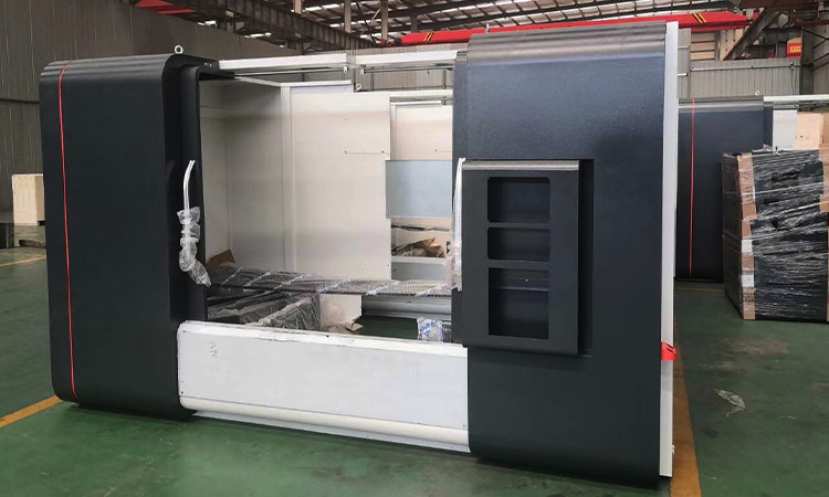
A traveling column vertical machining center is a CNC milling machine where the cutting column moves along a travel axis while the table supports the workpiece. Unlike a fixed-column vertical machining center, this design can provide a longer machining envelope without requiring the worktable to travel across the full length of the machine. The spindle head typically moves vertically on the column, while the column runs on linear guideways or a comparable rail system. For factory planners, that distinction is important. The machine footprint includes more than the bed and electrical cabinet; it also includes the column travel path, door swing, operator access, chip conveyor, maintenance clearance, and loading route. A reliable layout begins with the full machine envelope, not just the catalog dimensions.
Types of traveling column machining center
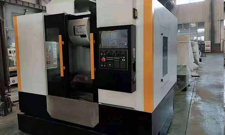
A traveling column machining center can be configured in several ways based on workpiece size, production volume, and material-handling requirements. Some models use a fixed table and a moving column on the longitudinal axis. Others combine column movement with a cross-sliding saddle or movable table, which changes loading, guarding, and access requirements. A machine may also include a standard three-axis spindle, fourth-axis rotary table, automatic tool changer, probing system, or chip conveyor. For small and medium-sized workpieces, a conventional vertical machining center may require less surrounding floor space because its table travel is shorter. For long castings, frames, plates, and structural parts, a column moving CNC machine can provide predictable loading positions while machining over a wider length.
Common configuration choices
- Fixed table and moving column: useful for long components and stable loading positions.
- Automatic tool changer: requires clearance for tool magazine access and service doors.
- Chip conveyor: changes rear or side clearance requirements and affects coolant recovery.
- Fourth-axis integration: requires additional rotary-table swing and workholding clearance.
- Manual or crane loading: needs a clear route from receiving, staging, or inspection areas.
When comparing models, buyers should request a general arrangement drawing that shows maximum travel, guarding, control pendant position, and access doors. The stated machine width may not include the control cabinet, chip conveyor, coolant tank, or transformer. It is also worth confirming whether the table sits at a practical loading height and whether service work is performed from the front, side, or rear. These details often influence aisle width more than one length or width measurement. MAKCNC offers several vertical CNC machining center MV1380 configurations, and the final layout should be checked against the selected specification rather than a general product category.
Features that affect the vertical machining center layout
The most significant layout factor is the moving mass. As the column travels, guards, cable carriers, and lubrication lines must remain clear of walls, pallets, stored material, and pedestrian routes. Mark the maximum left and right positions of the column on the floor plan, then add the safety margin recommended by the machine builder. Operators usually need access at the front, while maintenance may require access at the rear or along both sides. The control cabinet door, electrical disconnect, coolant tank, and chip conveyor service panels should open fully without obstructing an emergency exit or forklift lane. A crowded cell may still operate, but cleaning, troubleshooting, and tool changes will become slower and less safe.
Access zones and operator movement
Treat the front of the machine as an active work zone, not as unused open floor. The operator may need to open the enclosure, load a fixture, remove a finished component, inspect tool wear, and clear chips from the work area. Leave sufficient room for the largest expected component as well as the pallet jack or cart used to deliver it. If overhead crane loading is planned, confirm that the crane hook can reach the spindle-side work area without striking the enclosure, lighting, or nearby structures. The control pendant should be visible from the loading position, and the operator should never need to stand in the path of a moving column. MAKCNC’s vertical CNC machining center MV1270 can be assessed using the same front-access and travel-clearance approach.
Floor markings help turn a layout drawing into a practical work cell. Mark the machine boundary, operator position, raw-material staging area, finished-part rack, inspection point, and no-storage zones. Keep fire equipment, electrical panels, and emergency stops visible at all times. In many facilities, a marked pedestrian lane or guardrail separates people from powered traffic. Do not place temporary pallets, tooling cabinets, or coolant drums inside the moving-column envelope. These small obstructions often create awkward loading conditions and delay maintenance after installation. Reviewing the layout with the machine supplier before pouring the foundation is far less costly than relocating equipment later.
Traveling column vertical machining center application
This machine arrangement is well suited to manufacturers machining long aluminum plates, steel frames, welded structures, pump housings, mold bases, agricultural-machine components, and oilfield equipment. It can also support communication equipment frames, automotive fixtures, aerospace structural parts, and mineral-processing components when the work envelope and spindle package match the material. The best fit is typically a production cell with repeatable loading, a clear material route, and workpieces that benefit from a long machining range. It may be less suitable for a very small shop focused mainly on compact parts and the lowest possible initial footprint. In that situation, a standard vertical machine with a smaller table may offer easier access and lower facility requirements.
Material flow around the machine
Material flow should follow a straightforward direction: incoming stock to staging, staging to the machine, machine to inspection, and inspection to finished-goods storage. Avoid crossing the loading route with chip-bin movement or forklift traffic. Long workpieces need room for turning and orientation before entering the enclosure, particularly when they are lifted by crane. If parts are loaded manually, rack height should reduce bending and allow the operator to face the machine. If a pallet truck is used, verify its turning radius at the front of the enclosure. A separate quarantine area for nonconforming parts prevents rejected components from returning to the production queue. This type of planning reduces handling time while protecting finished surfaces.
CNC machine floor space and foundation planning
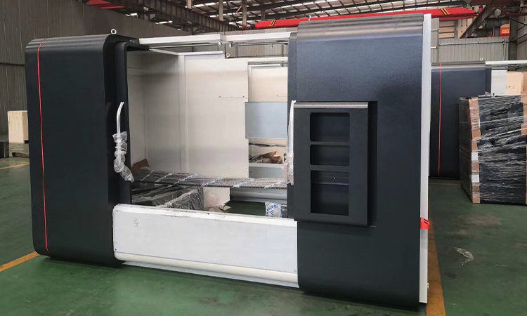
The required CNC machine floor space is greater than the machine’s listed footprint. Start with the supplier’s overall dimensions, then add the control cabinet, coolant system, chip conveyor, transformer, guarding, and maintenance access. Include a dedicated loading zone sized for the largest fixture and workpiece, not the average part. A machine with a 3,000 mm table or travel may require several additional meters for long-part staging and crane positioning. The exact allowance depends on the model and plant traffic, so the final drawing should be reviewed with the general arrangement file. Include door widths, ceiling height, column height, lifting points, and the route from the unloading door to the foundation.
Foundation work should be reviewed by a qualified local engineer together with the machine supplier. The slab must support the static weight, concentrated loads at leveling points, cutting forces, and dynamic effects created by acceleration and deceleration. Requirements may include a specified concrete strength, slab thickness, reinforcement pattern, anchor arrangement, leveling-pad locations, and flatness tolerance. Vibration from nearby stamping presses, forging equipment, compressors, or heavy vehicle traffic can affect surface finish and tool life. Do not assume that a thicker slab will solve every vibration issue. Isolation joints, machine orientation, and separation from vibration sources may be more effective. Buyers can compare published standards through the [ISO official standards site](https://www.iso.org/standards.html) and should obtain the machine-specific foundation drawing before construction begins.
Traveling column vertical machining center price factors
The price of a traveling column vertical machining center varies according to travel range, spindle power, spindle speed, table size, control system, tool capacity, linear scales, probing, rotary-axis preparation, coolant equipment, chip management, and automation. A longer travel range usually increases the size of the bed, guideways, enclosure, and shipping package. A high-speed spindle may require different bearings, cooling systems, and balancing specifications than a heavy-cutting spindle. The quotation should clearly separate the machine price from freight, export packing, installation, commissioning, operator training, tooling, foundation work, electrical connection, and optional chip conveyors. A lower purchase price may not result in a lower project cost if the machine requires major changes to doors, floors, cranes, or electrical distribution.
Ask each supplier for a detailed specification sheet and a list of included accessories. Confirm spindle taper, motor rating method, maximum table load, positioning accuracy, repeatability, working temperature range, controller brand, tool magazine capacity, and warranty terms. For production buyers, cycle-time testing on a representative workpiece is more useful than a general speed claim. Request references involving similar materials and component sizes. MAKCNC can also discuss customized CNC machines and machining centers from MAKCNC when a standard configuration does not match the planned cell, fixture, or loading method.
Traveling column vertical machining center user guide
Before installation, confirm the route from the truck or container unloading point to the foundation. Measure doors, ramps, turning areas, overhead beams, and floor load limits. Prepare electrical power, compressed air where required, coolant handling, lighting, and chip collection before the machine arrives. During installation, verify leveling, alignment, lubrication lines, coolant connections, and enclosure movement. Run the machine through its full axis travel at low speed before production begins. Check that the column does not approach a wall, rack, crane post, or guardrail at either end of travel. Record baseline positioning and repeatability results after commissioning so future maintenance checks have a meaningful reference.
Daily operation also influences the effectiveness of the layout. Keep the work area clear of loose fixtures, and assign fixed locations for tools, gauges, and workholding hardware. Remove chips with the installed conveyor, brush, or approved chip tool instead of placing hands near the cutting zone. Position coolant drums and chip bins so they can be replaced without entering the operator’s movement path. Schedule access to the rear cabinet and conveyor service points during planned maintenance. For export projects, ask whether the machine documentation includes electrical diagrams, lubrication instructions, CE-related files where applicable, and factory quality records such as ISO9001 documentation. These records help maintenance and safety teams prepare before commissioning.
Traveling column vertical machining center supplier
MAKCNC supplies CNC Lathing Machine, CNC Machining Center, and CNC Machine products for manufacturers, distributors, and project buyers. Its recommended machining-center and oilfield-lathe products are intended for automotive, aerospace, petroleum, agricultural machinery, chemical, mineral, water-conservancy, and geological-exploration applications. Buyers can review global CNC machinery cases of MAKCNC to compare application references and learn more about the company as a professional CNC lathing machine manufacturer. When requesting a quotation, provide the workpiece drawing, material, maximum dimensions, target tolerance, production quantity, available floor area, crane capacity, power supply, and preferred chip-removal method.
MAKCNC can help narrow the machine choice between a traveling-column configuration, a standard vertical machining center, or a horizontal CNC machining center. The right selection depends on how the workpiece is loaded, how many faces require machining, and whether the factory has space for pallets or a rotary system. For smaller components or turning work, a CNC inclined bed lathe may be a better fit than a milling center. Share the proposed floor plan with the sales engineer so clearance, foundation, shipping, and service access can be reviewed together.
FAQ of traveling column vertical machining center
How much floor space does a traveling column vertical machining center need?
There is no single answer because the required area depends on machine travel, enclosure dimensions, control cabinet position, chip conveyor, maintenance access, and workpiece loading. Use the supplier’s overall drawing as the starting footprint, then add a front operator zone, side or rear service access, and staging space for raw and finished parts. A machine with a long table may need several meters beyond the enclosure for long components, crane positioning, or pallet movement. Also check the turning radius of the forklift or pallet truck. Keep emergency routes and electrical-panel access outside the storage zone. Before construction, request the exact model drawing, foundation plan, shipping dimensions, and recommended clearance from MAKCNC rather than estimating from a product photograph or catalog width.
How do you plan material flow around a traveling column machining center?
Map the complete route from receiving to raw-material storage, machine loading, inspection, finished-part storage, and shipping. Keep incoming material and finished parts on separate racks where possible, and position the raw rack near the front or side loading point without entering the moving-column envelope. Long parts need space for orientation, slings, fixtures, and safe hand positioning. Place chip bins where the conveyor can discharge without blocking the operator or forklift route. Inspection should be close enough to reduce travel, yet far enough away to avoid coolant splash and chip contamination. Mark pedestrian lanes, no-storage areas, and crane hook paths on the floor. A short, one-direction flow is generally easier to supervise than a layout that sends parts back across active traffic.
What foundation requirements support a traveling column vertical machining center?
Foundation requirements depend on the machine’s mass, leveling points, travel, cutting force, spindle power, and the condition of the existing slab. The supplier should provide concrete thickness, strength, reinforcement, anchor or leveling-pad details, flatness limits, and any isolation recommendations. A local structural engineer should confirm that the building floor can carry concentrated loads and that nearby vibration sources will not affect machining accuracy. Check whether the machine needs a separate foundation or can sit on an engineered industrial slab. Prepare anchor locations only after confirming the final machine drawing. After installation, the machine must be leveled and checked across its working travel. MAKCNC should review the proposed foundation and access route before the buyer pours concrete or orders major facility modifications.
Is a column moving CNC machine suitable for every factory?
No. It is a strong option when the workpiece is long, the machining envelope must be extended, or the table should remain in a stable loading position. It may not be the best choice for a compact job shop producing small parts, where a smaller fixed-column machine can use less floor space and simplify access. The planner should compare table load, spindle reach, fixture size, cycle time, loading method, service clearance, and future production growth. A machine that fits today’s part but leaves no room for a chip conveyor or larger fixture can quickly become restrictive. Review representative drawings and complete a layout check before selecting the final model.
Plan the cell with MAKCNC
Good floor planning protects productivity long after installation. Define the moving-column envelope, operator position, foundation, crane path, material racks, chip route, maintenance zone, and emergency access before placing an order. If you are looking for a traveling column vertical machining center supplier, contact MAKCNC for the latest quotation and a model-specific layout review. You can also compare the vertical CNC machining center MV1160 and related CNC machining solutions before finalizing your production cell. Send your part dimensions and available factory area to receive practical product guidance.